9946 3M, 9946 Datasheet - Page 15
9946
Manufacturer Part Number
9946
Description
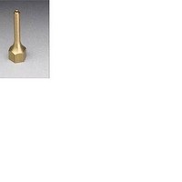
Soldering Tools .072 HOT MELT TIP SCOTCH WELD 3PC BAG
Manufacturer
3M
Type
Brass Extension Tipr
Datasheet
1.9946.pdf
(26 pages)
Specifications of 9946
Tip Size
0.072 mm
Product
Soldering Tips
Lead Free Status / Rohs Status
Lead free / RoHS Compliant
Other names
021200-22040
Available stocks
Company
Part Number
Manufacturer
Quantity
Price
Company:

Part Number:
994684-3
Manufacturer:
TE/AMP
Quantity:
30 000


Repair Procedures
13
Disconnect air and electrical power and make sure
applicator is at room temperature before servicing
3M™ Scotch-Weld™ Hot Melt Applicator PG II LT.
Failure to disconnect air and electrical power before
servicing may cause electrical shock or damage to the
applicator.
Procedure
C.
D.
G.
H.
A.
B.
E.
K.
F.
J.
I.
!
Caution
Handle Kit
Regulator Kit
Valve Kit
Hose Kit
Power Cord Kit
Switch Kit
Trigger Kit
Heat Shield Kit
Heater Kit
Thermostat/TCO Kit
Heat Block Kit
Part Kit
A. Handle Kit
Remove heat shield (see procedure H, page 16). With
the nozzle of the applicator pointing away from you,
remove the seven Phillips head cap screws in the
handle. These screws are located in the left hand side
of the handle grip, two in the pistol grip itself, two just
forward of the wire terminal and three to the rear of the
wire terminal. Without removing the wires from the
wire terminals, lift the handle up and to the front of the
applicator. This operation will allow for subsequent
repair steps.
To replace applicator handles, first follow “Handle
Disassembly Instructions.” Next remove the electrical
wiring from the terminal strip on the left handle,
replacing them to the same terminals on the
replacement. The right half of the handle is removed by
removing the four Phillips head cap screws. Next
remove the electrical wiring from the terminal strip and
re-assemble these to the replacement right half handle.
Lift the switch out of its slot in the handle and replace
it in the new handle. Replace the trigger and trigger pin
at this time. Using reverse procedure, reassemble the
right handle half, then the left. Be sure all the electrical
wires are in place and are not being pinched.
Handle Disassembly Instructions
© 3M 2006