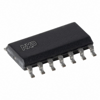
AU5783D,512 NXP Semiconductors, AU5783D,512 Datasheet - Page 5

AU5783D,512
Manufacturer Part Number
AU5783D,512
Description
IC TRANSCEIVER VPW 14-SOIC
Manufacturer
NXP Semiconductors
Series
AUr
Type
Transceiverr
Datasheet
1.AU5783D512.pdf
(14 pages)
Specifications of AU5783D,512
Number Of Drivers/receivers
1/1
Protocol
J1850
Voltage - Supply
5.5 V ~ 16 V
Mounting Type
Surface Mount
Package / Case
14-SOIC (3.9mm Width), 14-SOL
Lead Free Status / RoHS Status
Lead free / RoHS Compliant
Other names
568-3052-5
935263974512
AU5783D
935263974512
AU5783D
Philips Semiconductors
standby mode if the POR is tripped. Even if the device is not in
sleep mode the INH output will turn off at some battery voltages
below 4.4 V when the internal POR circuit is active. At still lower
voltages where the POR circuit does not operate, the INH may
again pull up toward the battery level, typically with battery voltages
below approximately 3.6 V. The operation of the POR circuit can be
verified by placing the device in the sleep mode while the battery
voltage is above 4.4 V. The INH output, which is a high side driver,
should turn off when the sleep mode is entered. Next ramp the
battery voltage down to 2.0V and finally return the battery voltage to
4.4 V. When the battery supply is returned to 4.4V, the INH output
will pull high since the device enters standby mode. The actual
voltages at which the POR engages and releases will vary from part
to part. The lowest voltage at which the POR will be active is 2.6 V
and it will always release below 4.4 V.
The AU5783 provides a high-speed data transmission mode where
the bus output waveshape function is disabled. In this mode transmit
signals are output as fast as possible thus allowing higher data
rates, e.g., the so-called 4X mode with 41.6 kbit/s nominal speed.
The AU5783 also provides a loop-back mode for diagnostic
purpose, e.g., self-test of an electronic control unit. In loop-back
mode the bus transmit and receive functions are disabled thus
2001 Feb 15
J1850/VPW transceiver with supply control function
6.7
5.5
4.2
3.9
3.4
1.9
8
È È È È È È È È È È È È È È È È
È È È È È È È È È È È È È È È È
È È È È È È È È È È È È È È È È
È È È È È È È È È È È È È È È È
È È È È È È È È È È È È È È È È
È È È È È È È È È È È È È È È È
È È È È È È È È È È È È È È È È
5.5 5.8
7
Figure 3. Bus voltage vs battery voltage
8
Battery Voltage (V)
5
essentially disconnecting an electronic control unit from the J1850
bus line. The TX signal is internally looped back to the RX output.
The AU5783 only requires one power supply V
transmissions can continue with battery voltage down to 5.5 V. The
bus output voltage will track 1.3V bellow the battery voltage. The
bus input voltage threshold will also follow the battery voltage going
down as shown in Figure 3. This ratio metric behavior of the input
threshold partially compensates for the reduced dominant level
transmitted during low battery operation.
The AU5783 features special robustness at its BAT and BUS pins
hence the device is well protected for applications in the automotive
environment. Specifically the BAT input is protected against 40 V
load dump and jump start condition. The BUS output is protected
against wiring fault conditions, e.g., short circuit to ground and
battery voltage as well as typical automotive transients and
electrostatic discharge. In addition, an over-temperature shutdown
function with hysteresis is incorporated which protects the device
under network fault conditions. In case of the die temperature
reaching the trip point, the AU5783 will latch-off the transceiver
function. The device is reset on the first rising edge on the TX input
after a decrease in the junction temperature.
16
È È È
È È È
Preliminary specification
BAT
bus output
bus input
. Bus
SL01254
AU5783


