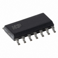
AU5783D,512 NXP Semiconductors, AU5783D,512 Datasheet - Page 8

AU5783D,512
Manufacturer Part Number
AU5783D,512
Description
IC TRANSCEIVER VPW 14-SOIC
Manufacturer
NXP Semiconductors
Series
AUr
Type
Transceiverr
Datasheet
1.AU5783D512.pdf
(14 pages)
Specifications of AU5783D,512
Number Of Drivers/receivers
1/1
Protocol
J1850
Voltage - Supply
5.5 V ~ 16 V
Mounting Type
Surface Mount
Package / Case
14-SOIC (3.9mm Width), 14-SOL
Lead Free Status / RoHS Status
Lead free / RoHS Compliant
Other names
568-3052-5
935263974512
AU5783D
935263974512
AU5783D
Philips Semiconductors
DC ELECTRICAL CHARACTERISTICS
7V < V
–2V < V
LWAKE connected to BAT via 10 k resistor; all voltages are referenced to pin 14 (GND); positive currents flow into the IC;
typical values reflect the approximate average value at V
2001 Feb 15
Pin BAT & thermal shutdown
Pins TX, NSTB
Pin 4X/LOOP
Pin LWAKE
Pin INH
Pin RX
J1850/VPW transceiver with supply control function
SYMBOL
I
I
I
I
I
I
T
T
V
V
I
I
I
V
I
I
V
I
V
–I
–I
V
V
–I
–I
–I
V
V
I
I
BAT.sl
BAT.sb
BAT.p.nl
BAT.p.h
BAT.wl
BAT.fl
ihtx
ih.nstb,nlh
il
ih-5
ih-3
ilb
ol_rx
oh_rx
sd
hys
ih
il
ih
ilb
il
i_wh
i_Wl
bat_POR
ol_rx
il
ils
I_w
oh_inh
ol_inh
BAT
bus
< 16 V; –40 C < T
< +9 V; NSTB = 5 V; 4X/LOOP = 5 V; R
Sleep mode supply current
Standby mode supply current
Supply current; passive state, in normal or
loopback modes
Supply current; passive state, in high
speed mode
Supply current; weak load
Supply current; full load
Thermal shutdown temperature
Thermal shutdown hysteresis
High level input voltage
Low level input voltage
TX high level input current
NSTB high level input current in normal,
loop back and high speed modes
Low level input current
High level input voltage (High Speed
Mode)
Mode)
High level input current with 5 V logic
High level input current with 3 V logic
Mid level input voltage (Loop back
operation)
Loopback mode input current
Low level input voltage (Normal Mode)
Low level input current
Low level input current in standby and
sleep mode
Local wake-up high
Local wake-up low
Low level input current
INH high level output current
INH off-state output leakage
Power-on reset release voltage; Battery
voltage threshold for setting INH output
high
Low level output voltage
Low level output current
High level output leakage
amb
PARAMETER
< +125 C; 250
s
< R
= 56 k
L
BAT
< 1.6 k ; 1.4 k < R
= 13 V and T
Note 1
Note 1
TX = 5 V; LWAKE = 0 V,
4X/LOOP = 0 or Z
TX = 5 V; LWAKE = 0 V,
4X/LOOP = 5 V
TX = 5 V, R
TX = 5 V, R
Note 2
Note 2
V
V
V
NSTB = 5 V
NSTB = 5 V, Bare Die
4X/LOOP = 5 V, NSTB = 5 V
4X/LOOP = 3 V, NSTB = 3 V
NSTB = 5 V
NSTB = 5 V; Note 4
NSTB = 5 V
V
V
NSTB = 0 V
NSTB = 0 V
V
V
4.9 V < V
V
NSTB = 0 V, BUS = 0 V,
V
I
all modes
V
V
RX
TX
NSTB
i
4X
4X
LWAKE
INH
INH
BAT
RX
RX
1%; RX connected to +5 V via R
= 0 V
= 1.6 mA, BUS = 7 V,
= 0 V, NSTB = 5 V
= 0 V, NSTB = 0 V
= 5 V
= 5 V, BUS = 7 V
= 5 V, BUS = 0 V, all modes
= V
= 0 V; NSTB = 0 V
= 4.4 V, verify INH = 1
= 5 V
= 0 V
BAT
BAT
8
CONDITIONS
amb
L
L
– 1 V;
= 1.38 k , Note 2
= 250
< 16 V
ld
= 25 C; unless otherwise specified.
< 12 k ;
d
= 3.9 k ; INH loaded with 100 k to GND;
155
5
2.7
50
10
–2
2.7
2.9
50
30
1.25
–2
50
–5
3.9
2
120
–5
0
2
–10
MIN.
TYP.
Preliminary specification
90
500
3
10
25
45
190
15
0.9
200
50
+2
300
250
1.65
2
+0.7
200
+5
2.5
25
500
+5
4.4
0.45
20
+10
MAX.
AU5783
mA
mA
mA
mA
V
V
V
V
V
V
V
V
V
V
mA
UNIT
C
C
A
A
A
A
A
A
A
A
A
A
A
A
A
A


