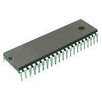
ST72C334N2B6 STMicroelectronics, ST72C334N2B6 Datasheet - Page 48

ST72C334N2B6
Manufacturer Part Number
ST72C334N2B6
Description
Microcontrollers (MCU) Flash 8K SPI/SCI
Manufacturer
STMicroelectronics
Datasheet
1.ST72C334N2T6.pdf
(126 pages)
Specifications of ST72C334N2B6
Data Bus Width
8 bit
Program Memory Type
Flash
Program Memory Size
8 KB
Data Ram Size
384 B
Interface Type
SCI, SPI
Maximum Clock Frequency
8 MHz
Number Of Programmable I/os
44
Number Of Timers
16 bit
Operating Supply Voltage
3.2 V to 5.5 V
Maximum Operating Temperature
+ 85 C
Mounting Style
Through Hole
Package / Case
SDIP-56
Minimum Operating Temperature
- 40 C
On-chip Adc
8 bit
Lead Free Status / Rohs Status
No
Available stocks
Company
Part Number
Manufacturer
Quantity
Price
Company:
Part Number:
ST72C334N2B6
Manufacturer:
ST
Quantity:
365
ST72334J/N, ST72314J/N, ST72124J
MISCELLANEOUS REGISTERS (Cont’d)
6.2.3 Miscellaneous Registers Description
MISCELLANEOUS REGISTER 1 (MISCR1)
Read/Write
Reset Value: 0000 0000 (00h)
Bit 7:6 = IS1[1:0] EI2 and EI3 sensitivity
The interrupt sensitivity, defined using the IS1[1:0]
bits, is applied to the following external interrupts:
EI2 (port B3..0) and EI3 (port B7..4). These 2 bits
can be written only when the I bit of the CC register
is set to 1 (interrupt disabled).
Bit 5 = MCO Main clock out selection
This bit enables the MCO alternate function on the
I/O port. It is set and cleared by software.
0: MCO alternate function disabled
1: MCO alternate function enabled
Note: To reduce power consumption, the MCO
function is not active in ACTIVE-HALT mode.
48/125
IS11 IS10
IS11
0
0
1
1
(I/O pin free for general-purpose I/O)
(f
7
OSC
IS10 MCO IS21
/2 on I/O port)
0
1
0
1
Falling edge & low level
Rising edge only
Falling edge only
Rising and falling edge
External Interrupt Sensitivity
IS20
CP1
CP0
SMS
0
Bit 4:3 = IS2[1:0] EI0 and EI1 sensitivity
The interrupt sensitivity, defined using the IS2[1:0]
bits, is applied to the following external interrupts:-
EI0 (port A3..0) and EI1 (port F2..0). These 2 bits
can be written only when the I bit of the CC register
is set to 1 (interrupt disabled).
Bit 2:1 = CP[1:0] CPU clock prescaler
These bits select the CPU clock prescaler which is
applied in the different slow modes. Their action is
conditioned by the setting of the SMS bit. These
two bits are set and cleared by software
Bit 0 = SMS Slow mode select
This bit is set and cleared by software.
0: Normal mode. f
1: Slow mode. f
See low power consumption mode and MCC
chapters for more details.
CP1 CP0
0
1
0
1
0
0
1
1
f
f
f
f
OSC
OSC
OSC
OSC
CPU
/ 4
/ 8
/ 16
/ 32
CPU
is given by CP1, CP0
f
CPU
=
f
OSC
in SLOW mode
/ 2


