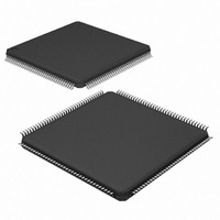
DP83816AVNG/NOPB National Semiconductor, DP83816AVNG/NOPB Datasheet - Page 43

DP83816AVNG/NOPB
Manufacturer Part Number
DP83816AVNG/NOPB
Description
IC MEDIA ACCESS CTRLR 144-LQFP
Manufacturer
National Semiconductor
Datasheet
1.DP83816AVNGNOPB.pdf
(106 pages)
Specifications of DP83816AVNG/NOPB
Applications
*
Interface
*
Voltage - Supply
*
Package / Case
144-LQFP
Mounting Type
Surface Mount
For Use With
DP83816-MAAP - BOARD EVALUATION DP83816
Lead Free Status / RoHS Status
Lead free / RoHS Compliant
Other names
*DP83816AVNG
*DP83816AVNG/NOPB
DP83816AVNG
*DP83816AVNG/NOPB
DP83816AVNG
Available stocks
Company
Part Number
Manufacturer
Quantity
Price
Company:
Part Number:
DP83816AVNG/NOPB
Manufacturer:
NS
Quantity:
5 000
Company:
Part Number:
DP83816AVNG/NOPB
Manufacturer:
Texas Instruments
Quantity:
10 000
Part Number:
DP83816AVNG/NOPB
Manufacturer:
NS/国半
Quantity:
20 000
4.0 Register Set
PMATCH[47:0] can be accessed via the combination of the RFCR (offset 0048h) and RFDR (offset 004Ch) registers.
PMATCH holds the Ethernet address info. See Section 3.3.3.
The lower 8 bits of the checksum value should be 55h. For the upper 8 bits, add the top 8 data bits to the lower 8 data bits
for each address. Sum the resultant 8 bit values for all addresses and then add 55h. Take the 2’s complement of the final
sum. This 2’s complement number should be the upper 8 bits of the checksum value in the last address.
As an example, consider an EEPROM with two addresses. EEPROM address 0000h contains the data 1234h. EEPROM
address 0001h contains the data 5678h.
12h + 34h = 46h
56h + 78h = CEh
46h + CEh + 55h = 69h
The 2’s complement of 69h is 97h so the checksum value entered into EEPROM address 0002h would be 9755h.
4.2.5 PCI Test Control Register
31-13
Bit
9-8
12
11
10
7
6
5
4
3
2
1
0
RBIST_RXFFAIL
RBIST_RXFAIL
RBIST_TXFAIL
RBIST_DONE
EEBIST_FAIL
EELOAD_EN
RBIST_RST
EEBIST_EN
Bit Name
RBIST_EN
Offset: 000Ch
(Continued)
Tag: PTSCR
unused
Reserved for NSC internal use only.
Must be written as a 0 otherwise. R/W
Reserved
SRAM BIST Reset
Setting this bit to 1 allows the SRAM BIST engine to be reset. R/W
Reserved for NSC internal use only.
Must be written as a 00 otherwise. R/W
SRAM BIST Enable
Setting this bit to 1 starts the SRAM BIST engine. R/W
SRAM BIST Done
This bit is set to one when the BIST has completed its current test. It is cleared when either the BIST
is active or disabled. RO
RX FIFO BIST Fail
This bit is set to 1 if the SRAM BIST detects a failure in the RX FIFO SRAM. RO
TX FIFO Fail
This bit is set to 1 if the SRAM BIST detects a failure in the TX FIFO SRAM. RO
RX Filter RAM BIST Fail
This bit is set to 1 if the SRAM BIST detects a failure in the RX Filter SRAM. RO
Enable EEPROM Load
This bit is set to a 1 to manually initiate a load of configuration information from EEPROM. A 1 is
returned while the configuration load from EEPROM is active (approx. 1500 us). R/W
Enable EEPROM BIST
This bit is set to a 1 to initiate EEPROM BIST, which verifies the EEPROM data and checksum
without reloading configuration values to the device. A 1 is returned while the EEPROM BIST is
active. R/W
EE BIST Fail indication
This bit is set to a 1 upon completion of the EEPROM BIST (EEBIST_EN returns 0) if the BIST logic
encountered an invalid checksum. RO
Access: Read Write
Size: 32 bits
43
Description
Hard Reset: 00000000h
Soft Reset: 00000000h
www.national.com


