A25LQ032N-F AMIC, A25LQ032N-F Datasheet - Page 5
A25LQ032N-F
Manufacturer Part Number
A25LQ032N-F
Description
58T1295
Manufacturer
AMIC
Datasheet
1.A25LQ032-F.pdf
(54 pages)
Specifications of A25LQ032N-F
Memory Type
Flash
Memory Size
32Mbit
Memory Configuration
32M X 1
Interface Type
Serial, SPI
Clock Frequency
100MHz
Supply Voltage Range
2.7V To 3.6V
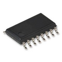
Memory Case Style
SOIC
No. Of Pins
16
Rohs Compliant
Yes


PIN DESCRIPTION
Chip Select (
The SPI Chip Select (
operation. When Chip Select (
deselected and the Serial Data Output (DO, or IO
IO
devices power consumption will be at standby levels unless
an internal erase, program or write status register cycle is in
progress.
When Chip Select (
selected, power consumption will increase to active levels
and instructions can be written to and data read from the
device. After power-up, Chip Select (
high to low before a new instruction will be accepted.
Serial Data Input, Output and IOs (DI, DO and IO
IO
The A25LQ032 support standard SPI, Dual SPI and Quad
SPI
unidirectional DI (input) pin to serially write instructions,
addresses or data to the device on the rising edge of the
Serial Clock (C) input pin. Standard SPI also uses the
unidirectional DO (output) to read data or status from the
device on the falling edge of Serial Clock (C).
Dual and Quad SPI instruction use the bidirectional IO pins
to serially write instructions, addresses or data to the device
on the rising edge of Serial clock (C) and read data or status
from the device on the falling edge of Serial Clock (C).
Quad SPI instructions require the non-volatile Quad Enable
bit (QE) in Status Register-2 to be set. When QE=1 the Write
Protect (
becomes IO
PRELIMINARY
3
3
) pins are at high impedance. When deselected, the
)
operation.
W
3
.
) pin becomes IO
S
)
(October, 2010, Version 0.3)
Standard
S
S
) is brought low the device will be
) pin enables and disables device
SPI
2
S
and Hold (
) is high the device is
instructions
S
) must transition from
HOLD
0
, IO
0
use
, IO
1
, IO
1
) pin
, IO
the
2
2
,
,
4
Write Protect (
The Write Protect (
Register from being written. Used in conjunction with the
Status Register’s Block Protect (CMP, SEC, TB, BP2, BP1
and BP0) bits and Status Register Protect (SRP1, SRP0) bits,
a portion or the entire memory array can be hardware
protected. The Write Protect (
When the QE bit of Status Register-2 is set for Quad I/O, the
Write Protect (
not available since this pin is used for IO
1b for the pin configuration of Quad I/O operation.
Hold (
The Hold (
it is actively selected. When Hold (
while Chip Select (
impedance and signals on the DI and Serial Clock (C) pins
will be ignored (don’t care). When Hold (
brought high, device operation can resume. The Hold
function can be useful when multiple devices are sharing the
same SPI signals. The Hold (
When the QE bit of Status Register-2 is set for Quad I/O. the
Hold (
used for IO
Quad I/O operation.
Serial Clock (C)
The SPI Serial Clock Input (C) pin provides the timing for
serial input and output operations.
HOLD
HOLD
HOLD
3
. See figure 1a and 1b for the pin configuration of
) pin function is not available since this pin is
)
W
W
) pin allows the device to be paused while
) pin (Hardware Write Protect) function is
)
W
S
) pin is low, the DO pin will be at high
) pin can be used to prevent the Status
AMIC Technology Corp.
HOLD
W
A25LQ032 Series
) pin is active low.
HOLD
) pin is active low.
2
. See figure 1a and
) pin is brought low,
HOLD
) pin is
Related parts for A25LQ032N-F
Image
Part Number
Description
Manufacturer
Datasheet
Request
R

Part Number:
Description:
2m X 16 Bit X 4 Banks Synchronous Dram - Amic Technology
Manufacturer:
AMIC Technology Corporation
Datasheet:

Part Number:
Description:
58T1324
Manufacturer:
AMIC
Datasheet:
Part Number:
Description:
Manufacturer:
AMIC Technology Corporation
Datasheet:
Part Number:
Description:
Manufacturer:
AMIC Technology Corporation
Datasheet:
Part Number:
Description:
Manufacturer:
AMIC Technology Corporation
Datasheet:
Part Number:
Description:
Manufacturer:
AMIC Technology Corporation
Datasheet:
Part Number:
Description:
Manufacturer:
AMIC Technology Corporation
Datasheet:
Part Number:
Description:
Manufacturer:
AMIC Technology Corporation
Datasheet:
Part Number:
Description:
Manufacturer:
AMIC Technology Corporation
Datasheet:
Part Number:
Description:
Manufacturer:
AMIC Technology Corporation
Datasheet:
Part Number:
Description:
Manufacturer:
AMIC Technology Corporation
Datasheet:
Part Number:
Description:
Manufacturer:
AMIC Technology Corporation
Datasheet:
Part Number:
Description:
Manufacturer:
AMIC Technology Corporation
Datasheet:
Part Number:
Description:
Manufacturer:
AMIC Technology Corporation
Datasheet:
Part Number:
Description:
Manufacturer:
AMIC Technology Corporation
Datasheet: