SC16C852SVIET,115 NXP Semiconductors, SC16C852SVIET,115 Datasheet - Page 18
SC16C852SVIET,115
Manufacturer Part Number
SC16C852SVIET,115
Description
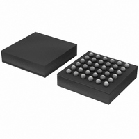
IC UART DL 1.8V W/FIFO 36-TFBGA
Manufacturer
NXP Semiconductors
Datasheet
1.SC16C852SVIET151.pdf
(48 pages)
Specifications of SC16C852SVIET,115
Features
Programmable
Number Of Channels
2, DUART
Fifo's
128 Byte
Protocol
RS485
Voltage - Supply
1.8V
With Auto Flow Control
Yes
With Irda Encoder/decoder
Yes
With False Start Bit Detection
Yes
With Modem Control
Yes
With Cmos
Yes
Mounting Type
Surface Mount
Package / Case
36-TFBGA
Lead Free Status / RoHS Status
Lead free / RoHS Compliant
Other names
935286451115
SC16C852SVIET-G
SC16C852SVIET-G
SC16C852SVIET-G
SC16C852SVIET-G
Available stocks
Company
Part Number
Manufacturer
Quantity
Price
Company:

Part Number:
SC16C852SVIET,115
Manufacturer:
NXP Semiconductors
Quantity:
10 000


NXP Semiconductors
7. Register descriptions
SC16C852SV_1
Product data sheet
6.13.3.2 Auto address detection
If Special Character Detect is enabled (EFR[5] is set and the XOFF2 register contains the
address byte), the receiver will try to detect an address byte that matches the
programmed character in the XOFF2 register. If the received byte is a data byte or an
address byte that does not match the programmed character in the XOFF2 register, the
receiver will discard these data. Upon receiving an address byte that matches the Xoff2
character, the receiver will be automatically enabled if not already enabled, and the
address character is pushed into the RX FIFO along with the parity bit (in place of the
parity error bit). The receiver also generates a line status interrupt (IER[2] must be set to
logic 1 at this time). The receiver will then receive the subsequent data from the ‘master’
station until being disabled by the controller after having received a message from the
‘master’ station.
If another address byte is received and this address byte does not match Xoff2 character,
the receiver will be automatically disabled and the address byte is ignored. If the address
byte matches Xoff2 character, the receiver will put this byte in the RX FIFO along with the
parity bit in the parity error bit (LSR bit 2).
Table 7
assigned bit functions are more fully defined in
details the assigned bit functions for the SC16C852SV internal registers. The
Dual UART with 128-byte FIFOs, IrDA, and XScale VLIO bus interface
Rev. 01 — 23 September 2008
Section 7.1
through
SC16C852SV
Section
© NXP B.V. 2008. All rights reserved.
7.24.
18 of 48
Related parts for SC16C852SVIET,115
Image
Part Number
Description
Manufacturer
Datasheet
Request
R

Part Number:
Description:
NXP Semiconductors designed the LPC2420/2460 microcontroller around a 16-bit/32-bitARM7TDMI-S CPU core with real-time debug interfaces that include both JTAG andembedded trace
Manufacturer:
NXP Semiconductors
Datasheet:

Part Number:
Description:
NXP Semiconductors designed the LPC2458 microcontroller around a 16-bit/32-bitARM7TDMI-S CPU core with real-time debug interfaces that include both JTAG andembedded trace
Manufacturer:
NXP Semiconductors
Datasheet:
Part Number:
Description:
NXP Semiconductors designed the LPC2468 microcontroller around a 16-bit/32-bitARM7TDMI-S CPU core with real-time debug interfaces that include both JTAG andembedded trace
Manufacturer:
NXP Semiconductors
Datasheet:
Part Number:
Description:
NXP Semiconductors designed the LPC2470 microcontroller, powered by theARM7TDMI-S core, to be a highly integrated microcontroller for a wide range ofapplications that require advanced communications and high quality graphic displays
Manufacturer:
NXP Semiconductors
Datasheet:
Part Number:
Description:
NXP Semiconductors designed the LPC2478 microcontroller, powered by theARM7TDMI-S core, to be a highly integrated microcontroller for a wide range ofapplications that require advanced communications and high quality graphic displays
Manufacturer:
NXP Semiconductors
Datasheet:
Part Number:
Description:
The Philips Semiconductors XA (eXtended Architecture) family of 16-bit single-chip microcontrollers is powerful enough to easily handle the requirements of high performance embedded applications, yet inexpensive enough to compete in the market for hi
Manufacturer:
NXP Semiconductors
Datasheet:
Part Number:
Description:
The XA-S3 device is a member of Philips Semiconductors? XA(eXtended Architecture) family of high performance 16-bitsingle-chip microcontrollers
Manufacturer:
NXP Semiconductors
Datasheet:

Part Number:
Description:
The NXP BlueStreak LH75401/LH75411 family consists of two low-cost 16/32-bit System-on-Chip (SoC) devices
Manufacturer:
NXP Semiconductors
Datasheet:
Part Number:
Description:
The NXP LPC3130/3131 combine an 180 MHz ARM926EJ-S CPU core, high-speed USB2
Manufacturer:
NXP Semiconductors
Datasheet:
Part Number:
Description:
The NXP LPC3141 combine a 270 MHz ARM926EJ-S CPU core, High-speed USB 2
Manufacturer:
NXP Semiconductors
Part Number:
Description:
The NXP LPC3143 combine a 270 MHz ARM926EJ-S CPU core, High-speed USB 2
Manufacturer:
NXP Semiconductors

Part Number:
Description:
The NXP LPC3152 combines an 180 MHz ARM926EJ-S CPU core, High-speed USB 2
Manufacturer:
NXP Semiconductors
Part Number:
Description:
The NXP LPC3154 combines an 180 MHz ARM926EJ-S CPU core, High-speed USB 2
Manufacturer:
NXP Semiconductors

Part Number:
Description:
Standard level N-channel enhancement mode Field-Effect Transistor (FET) in a plastic package using NXP High-Performance Automotive (HPA) TrenchMOS technology
Manufacturer:
NXP Semiconductors
Datasheet: