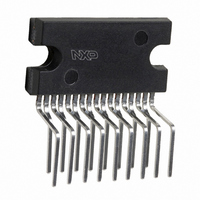
TDA8947J/N3,112 NXP Semiconductors, TDA8947J/N3,112 Datasheet - Page 7

TDA8947J/N3,112
Manufacturer Part Number
TDA8947J/N3,112
Description
IC AMP AUDIO PWR 29W QUAD 17SIL
Manufacturer
NXP Semiconductors
Type
Class ABr
Datasheet
1.TDA8947JN3112.pdf
(24 pages)
Specifications of TDA8947J/N3,112
Output Type
4-Channel (Quad)
Package / Case
17-SIL (Bent and Staggered Leads)
Max Output Power X Channels @ Load
29W x 2 @ 8 Ohm; 14W x 4 @ 4 Ohm
Voltage - Supply
9 V ~ 26 V
Features
Depop, Mute, Short-Circuit and Thermal Protection, Standby
Mounting Type
Through Hole
Product
Class-AB
Output Power
29 W
Available Set Gain
32 dB
Thd Plus Noise
0.05 %
Operating Supply Voltage
18 V
Maximum Power Dissipation
69000 mW
Maximum Operating Temperature
+ 85 C
Mounting Style
Through Hole
Audio Load Resistance
8 Ohms
Input Signal Type
Single
Minimum Operating Temperature
- 40 C
Output Signal Type
Differential, Single
Supply Type
Single
Supply Voltage (max)
26 V
Supply Voltage (min)
9 V
Lead Free Status / RoHS Status
Lead free / RoHS Compliant
Other names
568-3458-5
935274472112
TDA8947J
935274472112
TDA8947J
Philips Semiconductors
9397 750 14938
Product data sheet
8.4 Supply voltage ripple rejection
On — The amplifier is operating normally. The On mode is activated at
V
The output channels 3 and 4 can be switched on/off by applying a proper DC voltage to
pin MODE2, under the condition that the output channels 1 and 2 are in the On mode (see
Figure
Table 5:
The Supply Voltage Ripple Rejection (SVRR) is measured with an electrolytic capacitor of
150 F on pin SVR using a bandwidth of 20 Hz to 22 kHz.
as function of the frequency. A larger capacitor value on pin SVR improves the ripple
rejection behavior at the lower frequencies.
Voltage on pin
MODE1
0 V to 0.8 V
4.5 V to (V
(V
Fig 3. Mode selection
MODE1
CC
2.0 V) to V
3).
> (V
CC
Mode selection
CC
all standby
mdb016
3.5 V)
CC
2.0 V). The output of channels 3 and 4 can be set to Mute or On mode.
0.8
MODE2
0 V to V
0 V to V
0 V to (V
(V
Rev. 02 — 16 June 2005
CC
4.5
channels 3
2 V) to V
CC
CC
CC
3.5 V)
4: mute
all mute
CC
Channel 1 and 2
Standby mode
Mute mode
On mode
On mode
V
V
CC
CC
3.5
3.5
V
V
CC
channels 1
channels 3
channels 3
CC
© Koninklijke Philips Electronics N.V. 2005. All rights reserved.
Figure 11
2.0
2.0
4-channel audio amplifier
V
V
MODE1
MODE2
V
V
CC
CC
2: on
4: on or mute
4: on
Channel 3 and 4
(sub woofer)
Standby mode
Mute mode
Mute mode
On mode
TDA8947J
illustrates the SVRR
7 of 24


