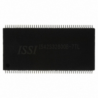
IS42S32800B-7TL ISSI, Integrated Silicon Solution Inc, IS42S32800B-7TL Datasheet - Page 17

IS42S32800B-7TL
Manufacturer Part Number
IS42S32800B-7TL
Description
IC SDRAM 256MBIT 143MHZ 86TSOP
Manufacturer
ISSI, Integrated Silicon Solution Inc
Datasheet
1.IS42S32800B-7BL.pdf
(62 pages)
Specifications of IS42S32800B-7TL
Package / Case
86-TSOPII
Memory Size
256M (8Mx32)
Format - Memory
RAM
Memory Type
SDRAM
Speed
143MHz
Interface
Parallel
Voltage - Supply
3 V ~ 3.6 V
Operating Temperature
0°C ~ 70°C
Data Bus Width
32 bit
Organization
2 Mbit x 32
Maximum Clock Frequency
143 MHz
Access Time
7 ns
Supply Voltage (max)
3.6 V
Supply Voltage (min)
3 V
Maximum Operating Current
150 mA
Maximum Operating Temperature
+ 70 C
Minimum Operating Temperature
0 C
Mounting Style
SMD/SMT
Lead Free Status / RoHS Status
Lead free / RoHS Compliant
Lead Free Status / RoHS Status
Lead free / RoHS Compliant, Lead free / RoHS Compliant
Other names
706-1025
Available stocks
Company
Part Number
Manufacturer
Quantity
Price
Company:
Part Number:
IS42S32800B-7TL
Manufacturer:
ISSI
Quantity:
1 000
Part Number:
IS42S32800B-7TL
Manufacturer:
ISSI
Quantity:
20 000
Company:
Part Number:
IS42S32800B-7TLI
Manufacturer:
ISSI
Quantity:
1 000
IS42S32800B
Integrated Silicon Solution, Inc.
Rev. F
07/21/09
Column Address
•
The Burst Type can be one of two modes,Interleave Mode or Sequential Mode.
A3
0
1
—Addressing Sequence of Sequential Mode
•
A column access is started in the input column address and is performed by inverting the address
bits in the sequence shown in the following table.
•
This field specifies the number of clock cycles from the assertion of the Read command to the first
read data.The minimum whole value of CAS#Latency depends on the frequency of CLK.The
minimum whole value satisfying the following formula must be programmed into this field.
t
Data n
Data 0
Data 1
Data 2
Data 3
Data 4
Data 5
Data 6
Data 7
CAC
Burst Length
(min)<=CAS#Latency X t
A6
0
0
0
0
1
Data n
Burst Type Field (A3)
Burst Type
Sequential
Interleave
An internal column address is performed by increasing the address from the column address which is input to the
device.The internal column address is varied by the Burst Length as shown in the following table.When the value
of column address,(n +m),in the table is larger than 255,only the least significant 8 bits are effective.
Addressing Sequence of Interleave Mode
CAS#Latency Field (A6~A4)
A5
0
0
1
1
X
A7
A7
A7
A7
A7
A7
A7
A7
A4
0
1
0
1
X
Full Page: Column address is repeated until terminated.
0
n
A6
A6
A6
A6
A6
A6
A6
A6
2 words:
4 words:
8 words:
Reserved
Reserved
2 clocks
3 clocks
Reserved
n+1
CAS#Latency
1
A5
A5
A5
A5
A5
A5
CK
A5
A5
n+2
2
Column Address
A4
A4
A4
A4
A4
A4
A4
A4
n+3
3
n+4
4
A3
A3
A3
A3
A3
A3
A3
A3
n+5
5
A2
A2
A2
A2
A2#
A2#
A2#
A2#
n+6
6
A1
A1
A1#
A1#
A1
A1
A1#
A1#
n+7
7
A0
A0#
A0
A0#
A0
A0#
-
A0
A0#
-
n+255
255
4 words
256
n
Burst Length
257
n+1
8 words
-
-
17


