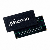
MT41J256M4HX-15E:D TR Micron Technology Inc, MT41J256M4HX-15E:D TR Datasheet - Page 152

MT41J256M4HX-15E:D TR
Manufacturer Part Number
MT41J256M4HX-15E:D TR
Description
IC DDR3 SDRAM 1GBIT 78FBGA
Manufacturer
Micron Technology Inc
Type
DDR3 SDRAMr
Specifications of MT41J256M4HX-15E:D TR
Format - Memory
RAM
Memory Type
DDR3 SDRAM
Memory Size
1G (256M x 4)
Speed
667MHz
Interface
Parallel
Voltage - Supply
1.425 V ~ 1.575 V
Operating Temperature
0°C ~ 95°C
Package / Case
78-FBGA
Organization
256Mx4
Density
1Gb
Address Bus
17b
Maximum Clock Rate
1.333GHz
Operating Supply Voltage (typ)
1.5V
Package Type
FBGA
Operating Temp Range
0C to 95C
Operating Supply Voltage (max)
1.575V
Operating Supply Voltage (min)
1.425V
Supply Current
220mA
Pin Count
78
Mounting
Surface Mount
Operating Temperature Classification
Commercial
Lead Free Status / RoHS Status
Lead free / RoHS Compliant
- Current page: 152 of 181
- Download datasheet (9Mb)
Table 74:
Figure 98: Active Power-Down Entry and Exit
PDF: 09005aef826aa906/Source: 09005aef82a357c3
1Gb_DDR3_4.fm - Rev. F 11/08 EN
DRAM State
Active (any bank open)
Precharged
(all banks precharged)
Command
Address
CK#
CKE
CK
Power-Down Modes
Valid
Valid
T0
t IH
t CK
Enter power-down
t IS
MR1[12]
mode
While in either power-down state, CKE is held LOW, RESET# is held HIGH, and a stable
clock signal must be maintained. ODT must be in a valid state but all other input signals
are a “Don’t Care.” If RESET# goes LOW during power-down, the DRAM will switch out of
power-down mode and go into the reset state. After CKE is registered LOW, CKE must
remain LOW until
down duration is
The power-down states are synchronously exited when CKE is registered HIGH (with a
required NOP or DES command). CKE must be maintained HIGH until
satisfied. A valid, executable command may be applied after power-down exit latency,
t
Table 74.
For certain CKE-intensive operations, for example, repeating a power-down exit to
refresh to power-down entry sequence, the number of clock cycles between power-down
exit and power-down entry may not be sufficient enough to keep the DLL properly
updated. In addition to meeting
power-down exit and power-down entry, two other conditions must be met. First,
must be satisfied before issuing the REFRESH command. Second,
fied before the next power-down may be entered. An example is shown in Figure 108 on
page 157.
XP
NOP
“Don’t
Care”
T1
1
0
t CH
t
XPDLL have been satisfied. A summary of the power-down modes is listed in
t CPDED
DLL State
t CL
NOP
Off
On
On
T2
t
PD (MAX) (9 ×
t
PD (MIN) has been satisfied. The maximum time allowed for power-
t PD
Power-Down
Slow
Exit
Fast
Fast
Ta0
t IH
152
t
t
PD when the REFRESH command is used in between
REFI).
Exit power-down
t
t
t
(READ, RDAP, or ODT on)
t
XP to any other valid command
XP to any other valid command
XPDLL to commands that require the DLL to be locked
XP to any other valid command
t IS
Micron Technology, Inc., reserves the right to change products or specifications without notice.
mode
NOP
Ta1
1Gb: x4, x8, x16 DDR3 SDRAM
Relevant Parameters
NOP
Ta2
t CKE (MIN)
Indicates A Break in
Time Scale
t XP
©2006 Micron Technology, Inc. All rights reserved.
NOP
t
Ta3
XPDLL must be satis-
t
CKE has been
Operations
Valid
Valid
Don’t Care
Ta4
t
XP
Related parts for MT41J256M4HX-15E:D TR
Image
Part Number
Description
Manufacturer
Datasheet
Request
R

Part Number:
Description:
Manufacturer:
Micron Technology Inc
Datasheet:

Part Number:
Description:
Manufacturer:
Micron Technology Inc
Datasheet:

Part Number:
Description:
IC SDRAM 64MBIT 133MHZ 54TSOP
Manufacturer:
Micron Technology Inc
Datasheet:

Part Number:
Description:
IC SDRAM 64MBIT 5.5NS 86TSOP
Manufacturer:
Micron Technology Inc
Datasheet:

Part Number:
Description:
IC SDRAM 64MBIT 200MHZ 86TSOP
Manufacturer:
Micron Technology Inc
Datasheet:

Part Number:
Description:
IC SDRAM 64MBIT 133MHZ 54TSOP
Manufacturer:
Micron Technology Inc
Datasheet:

Part Number:
Description:
IC SDRAM 128MBIT 133MHZ 54TSOP
Manufacturer:
Micron Technology Inc
Datasheet:

Part Number:
Description:
IC SDRAM 256MBIT 133MHZ 90VFBGA
Manufacturer:
Micron Technology Inc
Datasheet:

Part Number:
Description:
IC SDRAM 128MBIT 133MHZ 54TSOP
Manufacturer:
Micron Technology Inc
Datasheet:

Part Number:
Description:
IC SDRAM 256MBIT 133MHZ 54TSOP
Manufacturer:
Micron Technology Inc
Datasheet:

Part Number:
Description:
IC DDR SDRAM 512MBIT 6NS 66TSOP
Manufacturer:
Micron Technology Inc
Datasheet:

Part Number:
Description:
IC SDRAM 128MBIT 167MHZ 86TSOP
Manufacturer:
Micron Technology Inc
Datasheet:

Part Number:
Description:
IC SDRAM 128MBIT 143MHZ 86TSOP
Manufacturer:
Micron Technology Inc
Datasheet:

Part Number:
Description:
SDRAM 256M-BIT 1.8V 54-PIN VFBGA
Manufacturer:
Micron Technology Inc
Datasheet:

Part Number:
Description:
IC SDRAM 128MBIT 143MHZ 86TSOP
Manufacturer:
Micron Technology Inc
Datasheet:


