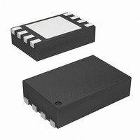
ISL6296ADRTZ-T Intersil, ISL6296ADRTZ-T Datasheet - Page 17

ISL6296ADRTZ-T
Manufacturer Part Number
ISL6296ADRTZ-T
Description
IC AUTHENTICATION DEVICE 8-TDFN
Manufacturer
Intersil
Series
FlexiHash™r
Datasheet
1.ISL6296ADHZ-T.pdf
(20 pages)
Specifications of ISL6296ADRTZ-T
Function
Battery Authentication
Battery Type
Li-Ion, Li-Pol, NiMH
Voltage - Supply
2.6 V ~ 4.8 V
Operating Temperature
-25°C ~ 85°C
Mounting Type
Surface Mount
Package / Case
8-TDFN Exposed Pad
Lead Free Status / RoHS Status
Lead free / RoHS Compliant
Available stocks
Company
Part Number
Manufacturer
Quantity
Price
Company:
Part Number:
ISL6296ADRTZ-T
Manufacturer:
INTERSIL
Quantity:
1 000
Company:
Part Number:
ISL6296ADRTZ-TR5302
Manufacturer:
RENESAS
Quantity:
32 462
Part Number:
ISL6296ADRTZ-TR5302
Manufacturer:
INTERSIL
Quantity:
20 000
ADDRESS 0-0E/0F: GENERAL PURPOSE MEMORY
(INF1/2)
These address locations can be used to store information
like model ID, date code, and other cell information, which
can be read by the host.
ADDRESS 1-00: MASTER CONTROL REGISTER (MSCR)
The Master Control Register is defined in Table 14. The
MSCR register can be both read or written by the host
through the XSD bus.
ADDRESS 1-01: DEVICE STATUS REGISTER (STAT)
The STAT register is defined in Table 15. All status bits will
be cleared upon a read to this register. The STAT is a
read-only register.
ADDRESS 2-00: SECRETS SELECTION REGISTER
(SESL)
This register must be written to re-load the hash engine with
secrets stored in OTP ROM prior to presenting a new
challenge code word input.
ADDRESS 2-01: CHALLENGE CODE INPUT REGISTER
(CHLG)
This register is used to input the 32-Bit challenge code
generated by the host for device authentication. All four
bytes of the challenge code should be written sequentially to
this register, starting with the least-significant byte. After the
fourth challenge byte is received, the authentication code
generation process will start. This CHLG is a write-only
register.
ADDRESS 2-05: AUTHENTICATION CODE OUTPUT
REGISTER (AUTH)
This register is used to output the 8-Bit authentication code
calculated from the 32-Bit challenge code. The register
content may be read only once after each challenge code
word is written to the device. Subsequent read to this
register without a new challenge being input will result in an
error condition.
BIT
7:4
3:2
1:0
CSL[1:0]
SSL[1:0]
NAME
--
TYPE
RW
RW
R
17
DEFAULT
0000
01
10
TABLE 16. SECRETS SELECTION REGISTER (SESL)
Unused
Coefficient Definition Secret Selection: Selects the authentication secret code word stored in
OTP ROM to be used as the coefficient definition code for the FlexiHash engine.
00: invalid selection
01: Authentication Secret Set #1
10: Authentication Secret Set #2
11: Authentication Secret Set #3
Seed Secret Selection: Selects the authentication secret code word stored in OTP ROM to be
used as the secret seed for the FlexiHash engine.
00: invalid selection
01: Authentication Secret Set #1
10: Authentication Secret Set #2
11: Authentication Secret Set #3
ISL6296A
Applications Information
XSD Bus Implementation
There are two ways to implement the XSD host in a
microprocessor. One way is to use a spare UART (Universal
Asynchronous Receiver/Transmitter). A GPIO (General
Purpose Input/Output) can be used if no UART is available
for the XSD communication. Refer to Application Note
AN1167 available from Intersil for more information
regarding how to implement the XSD bus within a
microprocessor.
Pull-Up Resistor Selection
Since there is an internal pull-down current on the XSD pin,
(as shown in Figure 8), it is important to choose a pull-up
resistor value that is low enough so that the small amount of
pull-down current through the resistor does not cause the
bus voltage to droop below the V
condition. 5kΩ is a typical resistance used for pull-up.
Powered by XSD Bus
In applications where the device supply voltage is lower than
2.6V (such as an application powered by a single-cell NiMH
battery), or a device that has no power source at all, the
ISL6296A can be powered by the XSD bus. The application
circuit is shown in Figure 2. The condition for the application
circuit to function properly is that the bus pull-up voltage is
3.3V or 5V. The bus pull-up voltage will charge the capacitor
C
ESD diode has 0.4V drop typically.
ESD Rating
The ISL6296A ESD specification is rated at 4kV of the
human body model. When the ISL6296A is used in a
handheld accessory, a higher ESD rating is typically
required. External components are required to enhance the
ESD performance.
1
through an internal ESD diode, as shown in Figure 8. The
DESCRIPTION
IH
specification under any
April 15, 2010
FN6567.3


