DS1862B+ Maxim Integrated Products, DS1862B+ Datasheet - Page 39
DS1862B+
Manufacturer Part Number
DS1862B+
Description
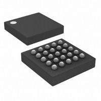
IC LASR CTRLR 7CHAN 5.5V 25CSBGA
Manufacturer
Maxim Integrated Products
Type
Laser Diode Controller (Fiber Optic)r
Datasheet
1.DS1862B.pdf
(43 pages)
Specifications of DS1862B+
Data Rate
10Gbps
Number Of Channels
7
Voltage - Supply
2.9 V ~ 5.5 V
Current - Supply
3mA
Operating Temperature
-40°C ~ 100°C
Package / Case
25-CSBGA
Mounting Type
Surface Mount
Lead Free Status / RoHS Status
Lead free / RoHS Compliant


Packet error checking during reads is supported by the
DS1862. Information is transferred form the DS1862 in
much the same way as conventional I
ever, an extra CRC field is added and checked. The
master still begins by sending the device address (A0h
for DS1862), then the index pointer to the memory
address of interest. The next byte transferred, however,
is the value of the intended number of bytes to be read.
The calculation of the CRC-8 includes and requires the
explicit starting memory address to be included as the
second transferred byte (dummy write byte). Next, the
slave transfers the data back as the master acknowl-
edges. Only 1 to 128 bytes can be sequentially read
during one transmission while using PEC. After the
master reads the intended number of bytes, the CRC-8
value is transmitted by the DS1862. The master ends
Figure 15. I
COMMUNICATIONS KEY
WRITE UP TO A 4-BYTE PAGE WITH A SINGLE TRANSACTION
WRITE A SINGLE BYTE
READ A SINGLE BYTE WITH A DUMMY WRITE CYCLE TO SET THE ADDRESS COUNTER
READ MULTIPLE BYTES WITH A DUMMY WRITE CYCLE TO SET THE ADDRESS COUNTER
SR
S
P
S
S
S
S
1 0 1
1 0 1
1 0 1
1 0 1
START
STOP
REPEATED
START
2
XFP Laser Control and Digital Diagnostic IC
C Communications Examples
0
0
0
0
A
N
0
0
0
0
DATA
Packet Error Checking
0
X X X X X X X X
0
0
0
NOT
ACK
ACK
0 0
0 0
0 0
0 0
I
2
Packet Error Checking
C Operation Using
Read Operation with
A
A
A
A
A
SHADED BOXES INDICATE THE SLAVE IS
CONTROLLING SDA
WHITE BOXES INDICATE THE MASTER IS
CONTROLLING SDA
MEMORY ADDRESS
MEMORY ADDRESS
MEMORY ADDRESS
MEMORY ADDRESS
2
____________________________________________________________________
C protocol, how-
8-BIT ADDRESS OR DATA
DATA
A
A
A
A
SR
SR
1 0 1
1 0 1
the communication with a NACK and a STOP. See
Figure 16 for a graphical representation. The CRC-8 is
calculated starting with the MSB of the memory
address pointer, number of bytes to read, and the read
data. The master can then verify the CRC-8 value and
reject the read data if the CRC-8 value does not corre-
spond to the received CRC value. The CRC-8 must be
calculated by using the following polynomial for both
reads and writes:
Packet error checking during writes is also supported
by the DS1862. Information is written to the DS1862 in
much the same way as conventional I
ever, an extra CRC field is added and checked. The
master still begins by sending the device address, then
the index pointer to the memory address of interest.
The next byte, however, is the value of the intended
number of bytes to be written. The calculation of the
DATA
DATA
A
0
0
0
0
0
0
0 0
DATA
0 0
NOTE:
ALL BYTES ARE SENT MOST SIGNIFICANT BIT FIRST.
THE FIRST BYTE SENT AFTER A START CONDITION IS
ALWAYS THE SLAVE ADDRESS FOLLOWED BY THE
READ/WRITE BIT.
A
A
C(x) = X
P
A
A
8
Packet Error Checking
+X
N
Write Operation with
2
DATA
DATA
P
+ X + 1
DATA
2
C protocol, how-
N
A
A
P
P
39
Related parts for DS1862B+
Image
Part Number
Description
Manufacturer
Datasheet
Request
R

Part Number:
Description:
XFP Laser Control and Digital Diagnostic IC
Manufacturer:
Maxim Integrated Products
Part Number:
Description:
MAX7528KCWPMaxim Integrated Products [CMOS Dual 8-Bit Buffered Multiplying DACs]
Manufacturer:
Maxim Integrated Products
Datasheet:
Part Number:
Description:
Single +5V, fully integrated, 1.25Gbps laser diode driver.
Manufacturer:
Maxim Integrated Products
Datasheet:
Part Number:
Description:
Single +5V, fully integrated, 155Mbps laser diode driver.
Manufacturer:
Maxim Integrated Products
Datasheet:
Part Number:
Description:
VRD11/VRD10, K8 Rev F 2/3/4-Phase PWM Controllers with Integrated Dual MOSFET Drivers
Manufacturer:
Maxim Integrated Products
Datasheet:
Part Number:
Description:
Highly Integrated Level 2 SMBus Battery Chargers
Manufacturer:
Maxim Integrated Products
Datasheet:
Part Number:
Description:
Current Monitor and Accumulator with Integrated Sense Resistor; ; Temperature Range: -40°C to +85°C
Manufacturer:
Maxim Integrated Products
Part Number:
Description:
TSSOP 14/A�/RS-485 Transceivers with Integrated 100O/120O Termination Resis
Manufacturer:
Maxim Integrated Products
Part Number:
Description:
TSSOP 14/A�/RS-485 Transceivers with Integrated 100O/120O Termination Resis
Manufacturer:
Maxim Integrated Products
Part Number:
Description:
QFN 16/A�/AC-DC and DC-DC Peak-Current-Mode Converters with Integrated Step
Manufacturer:
Maxim Integrated Products
Part Number:
Description:
TDFN/A/65V, 1A, 600KHZ, SYNCHRONOUS STEP-DOWN REGULATOR WITH INTEGRATED SWI
Manufacturer:
Maxim Integrated Products
Part Number:
Description:
Integrated Temperature Controller f
Manufacturer:
Maxim Integrated Products
Part Number:
Description:
SOT23-6/I�/45MHz to 650MHz, Integrated IF VCOs with Differential Output
Manufacturer:
Maxim Integrated Products
Part Number:
Description:
SOT23-6/I�/45MHz to 650MHz, Integrated IF VCOs with Differential Output
Manufacturer:
Maxim Integrated Products
Part Number:
Description:
EVALUATION KIT/2.4GHZ TO 2.5GHZ 802.11G/B RF TRANSCEIVER WITH INTEGRATED PA
Manufacturer:
Maxim Integrated Products