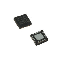
LDS8160-002-T2 IXYS, LDS8160-002-T2 Datasheet - Page 14

LDS8160-002-T2
Manufacturer Part Number
LDS8160-002-T2
Description
IC LED DVR WHT/RGB BCKLGT 16WQFN
Manufacturer
IXYS
Series
LED-Sense™, Power-Lite™r
Type
Backlight, White LED, RGB (I²C Interface)r
Datasheet
1.LDS8160-002-T2.pdf
(39 pages)
Specifications of LDS8160-002-T2
Topology
Linear (LDO), PWM
Number Of Outputs
6
Internal Driver
Yes
Type - Primary
Backlight
Type - Secondary
RGB, White LED
Frequency
1.2MHz
Voltage - Supply
2.3 V ~ 5.5 V
Mounting Type
Surface Mount
Package / Case
16-WQFN, 16-miniQFN
Operating Temperature
-40°C ~ 85°C
Current - Output / Channel
25mA
Internal Switch(s)
Yes
Efficiency
80%
Lead Free Status / RoHS Status
Lead free / RoHS Compliant
Voltage - Output
-
Lead Free Status / Rohs Status
Details
Other names
LDS8160-002-T2-2
LDS8160
Control Register (1Fh)
calibration sequence of the LDS8160 LED-Sense
temperature compensation circuits. The calibration
process takes approximately 16 ms.
The user can then additionally program the DC
current and PWM duty cycles for the LEDs. A PWM
ramp-up sequence occurs after the writing to the
PWM registers. This ramp-up delay in less than 250
ms in the default soft-start ramp mode, or can be 64
ms using the optional fast (4x) ramp mode (bit 3 of
Register 19h = HIGH). A further option is available to
bypass the soft-start PWM ramp mode entirely and
the initialization time will be reduced to just the
calibration sequence time of ~ 16ms. The initial soft-
start ramp mode can be bypassed by setting bit 4 of
register 19h HIGH.
The calibration parameters for the temperature
measurement
parameters remain intact until the part is reset or
powered-down. Additionally, the user can re-calibrate
LDS8160 during times when LED currents are
brought to zero and the system is thermally stabilized
by programming the calibration command bit as
discussed.
Factory preset values (upon completion of the power-
up initialization but prior to user programming) are as
follow (see Table3):
LED Current Setting
Current setting registers 00h – 02h should be
programmed using I
should be enabled using register 03h before LEDs
turn on.
The standard I
program I
LDS8160 should be addressed with slave address
chosen followed by register address (00h, 01h, or
© 2009 IXYS Corp.
Characteristics subject to change without notice
a) All LEDs are disabled and I
b) RGB
c) PWM dimming control in Logarithmic Mode
d) LED temperature compensation enabled with
e) Internal Diode for temperature compensation
f)
Luminosity vs. Temperature correction tables
(LUTs) selected and three PWM generators;
with PWM generators running by 120
shift;
LUTs
start/shutdown enabled;
is enabled
LEDs are used as sensors for temperature
compensation control.
LED
current (see section “I
2
mode
C interface procedure is used to
engine
in
2
C interface and desired LEDs
Logarithmic
with
and
HIGH. This starts the
three
all
LEDA, B, C
2
C INTERFACE”).
Mode
customer-set
independent
= 0;
0
phase
Soft
TM
14
02h) and data that represents the code for the
desired LED current. (See Table 10 for accessible
slave addresses.)
Code for LED current is determined as I
in hex format, i.e. 20 mA current code = 20/0.125 =
160 (dec) = A0h.
The LDS8160 maximum current should not exceed
25 mA per LED (i.e. current code should not exceed
200 (dec) = C8h) to meet all electrical specifications.
To turn LEDs ON/OFF register 03h should be
addressed with data that represents the desired
combination of LEDs turned ON/OFF (see Table 1);
i.e. if LEDC1, LEDC2, LEDA1, LEDA2 should be ON,
and LEDB1, LEDB2 should be OFF, binary code that
should be written into register 03h is 110011 (bin) =
33h.
The LDS8160 allows two ways for LED current
setting. One of them is using registers 00h – 02h
(static mode) and other one by using the PWM signal
to decrease average LED current value set by these
registers (dynamic mode).
For dynamic mode, the LDS8160 integrates 3 digital
PWM generators that operate at a frequency of ~ 285
Hz. In Logarithmic Mode, the PWM generators are
12-bit resolution and can be programmed with an 8-
bit code to provide 256 internally mapped 12-bit
logarithmic duty cycle steps to adjust the dimming
level. In Linear Mode, the PWM generates 256 linear
duty cycle steps to adjust the dimming levels from the
user programmed 8-bit code.
The advantage of PWM dimming is stable LED color
temperature / wavelength that are determined by the
maximum LED current value set by registers 00h –
02h.
To use the dynamic PWM mode for LED current
setting, the maximum I
registers 00h – 02h as described above in static
mode and the desired PWM dimming should be set
by registers 05h – 07h. In Logarithmic Mode, set by
default, dimming resolution is approximately -0.17 dB
per step with 0dB dimming, or 100% duty cycle, at
the 256
Global PWM Dimming
The LDS8160 allows Global PWM Dimming control of
all three banks in the RGB Logarithmic mode, set by
default. It is convenient, because it allows the user to
simultaneously change LED brightness equally
across to all three channels independent of the
maximum static current setting (registers 00h, 01h
and 02h) in a particular channel.
th
step.
LED
value should be first set by
Doc. No. 8160_DS, Rev. N1.0
LED
/0.125 mA


