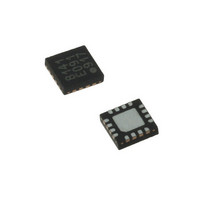
LDS8160-002-T2 IXYS, LDS8160-002-T2 Datasheet - Page 7

LDS8160-002-T2
Manufacturer Part Number
LDS8160-002-T2
Description
IC LED DVR WHT/RGB BCKLGT 16WQFN
Manufacturer
IXYS
Series
LED-Sense™, Power-Lite™r
Type
Backlight, White LED, RGB (I²C Interface)r
Datasheet
1.LDS8160-002-T2.pdf
(39 pages)
Specifications of LDS8160-002-T2
Topology
Linear (LDO), PWM
Number Of Outputs
6
Internal Driver
Yes
Type - Primary
Backlight
Type - Secondary
RGB, White LED
Frequency
1.2MHz
Voltage - Supply
2.3 V ~ 5.5 V
Mounting Type
Surface Mount
Package / Case
16-WQFN, 16-miniQFN
Operating Temperature
-40°C ~ 85°C
Current - Output / Channel
25mA
Internal Switch(s)
Yes
Efficiency
80%
Lead Free Status / RoHS Status
Lead free / RoHS Compliant
Voltage - Output
-
Lead Free Status / Rohs Status
Details
Other names
LDS8160-002-T2-2
LDS8160
© 2009 IXYS Corp.
Characteristics subject to change without notice
ADDRESS DESCRIPTION
`
50h – 5Fh
60h – 6Fh
70h – 7Fh
1Dh
1Ch
1Eh
1Fh
4Ah
4Bh
A0h
19h
49h
Digital Test Mode
LED shorted to GND
LED Fault Detected
(LED shorted to V
open)
Configuration register
Software reset, Standby
Ta-Tj Temperature
Offset
LED shutdown
Temperature
2-x Table enable and
breakpoint (T-code)
LUT-B
Δ PWM code1[7:4],
Δ PWM code0[3:0] –
Δ PWM code31[7:4],
Δ PWM code30[3:0]
LUT-G
Δ PWM code1[7:4],
Δ PWM code0[3:0] –
Δ PWM code31[7:4],
Δ PWM code30[3:0]
LUT-R
Δ PWM code1[7:4],
Δ PWM code0[3:0] –
Δ PWM code31[7:4],
Δ PWM code30[3:0]
Silicon diode dV
F
/dT [7:0]
IN
or
BITS
8
6
6
8
8
8
5
6
8
8
8
8
NOTES
See Table 2; Bit 5 = 1 sets user-initiated LED short/open
diagnostic
Bits from bit 5 to bit 0 represent LED status for LEDC2 –
LEDA1 respectively. Bit = 1 represents LED shorted to GND
When the corresponding bit in the “faults” detection register,
1Dh, is also High=1, and the associated LED driver current is
disabled.
Bits from bit 5 to bit 0 represent LED status for LEDC2 –
LEDA1 respectively. Bit = 1 represents that an LED Fault is
detected. If the corresponding bit in register 1Ch is also High
=1, than the LED is shorted to ground and current driver is
disabled. If the corresponding bit in register 1Ch is Low=0 than
the LED is either shorted to V
See Table 3
See Table 4
Two 4-bit compensation offsets between Ta and Tj:
Bit [7:4] = temperature offsets for LED temperature
Bit [3:0] = temperature offset for Silicon diode temperature
Each LSB = 5°C; temperature adjustment range from -40
+35
Code 1000 in either nibble = -40ºC offset; Code 0111 in either
nibble = +35ºC offset. See Tables 5 and 6
Defines T-code, at which LED current shuts down per LED
vendor de-rating specification (see Table 7); Factory default
value = 11100 (bin) = 1Ch represents 105
Bit 5 = 1 – enable 2-x scale LUT Δ PWM code correction (de-
rating) starting at the breakpoint set by T-code (bits 4:0)
Bit 5 = 0 – 1-x scale (default) for entire temperature range
Bit [4:0] defines T-code, where temperature derating starts, or
where 2-x scaling begins (see Table 7)
1-x scale is ~ ± 0.17dB per step
2-x scale is ~ ± 0.34dB per step
Two LUT words per I
Each word contains two 4-bit numbers representing of Δ PWM
codes.
See Table 8 and Appendix 1 for LUT programming.
Coding is different for Logarithmic and Linear Modes.
See above:
See above:
Silicon diode V
Factory recommended value = -1.71 mV/°C = 001 10110
(bin) = 36h,
where bits from bit 7 to bit 5 represent integer part [1(decimal)
= 001 (bin)], and bits from bit 4 to bit 0 – fractional part [0.710 /
0.03125 = 22 (decimal) = 10110 (bin)]
7
0
C
F
temperature coefficient :
2
C address.
IN
or open
Doc. No. 8160_DS, Rev. N1.0
0
C.
0
C to


