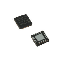
LDS8160-002-T2 IXYS, LDS8160-002-T2 Datasheet - Page 17

LDS8160-002-T2
Manufacturer Part Number
LDS8160-002-T2
Description
IC LED DVR WHT/RGB BCKLGT 16WQFN
Manufacturer
IXYS
Series
LED-Sense™, Power-Lite™r
Type
Backlight, White LED, RGB (I²C Interface)r
Datasheet
1.LDS8160-002-T2.pdf
(39 pages)
Specifications of LDS8160-002-T2
Topology
Linear (LDO), PWM
Number Of Outputs
6
Internal Driver
Yes
Type - Primary
Backlight
Type - Secondary
RGB, White LED
Frequency
1.2MHz
Voltage - Supply
2.3 V ~ 5.5 V
Mounting Type
Surface Mount
Package / Case
16-WQFN, 16-miniQFN
Operating Temperature
-40°C ~ 85°C
Current - Output / Channel
25mA
Internal Switch(s)
Yes
Efficiency
80%
Lead Free Status / RoHS Status
Lead free / RoHS Compliant
Voltage - Output
-
Lead Free Status / Rohs Status
Details
Other names
LDS8160-002-T2-2
LDS8160
Appendix 1 describes how to generate PWM LUT
correction profiles. Additionally software tools and
support is available from the factory to assist
customers to generate LUT tables for specific LEDs
and applications. Please consult the factory or a
sales representative.
Global Dimming Limitations
The final PWM dimming code value is the algebraic
sum of three codes: Dynamic Dimming code, Global
Dimming Code, and the Temperature Compensation
Code. If this sum is equal to or below zero, the LED
in that particular channel is disabled. It means that
the Global Dimming dynamic range is limited by
Dynamic Dimming and the Temperature Correction
Table used.
As an example:
If the user set PWM Dynamic Dimming in a particular
channel is set to -20 dB (registers 05h – 07h data =
code 143 (dec)) and the LED-Sense
vs. PWM Correction requires 7 steps correction
dimming (data code 7 (dec)), the resultant allowable
additional Global Dimming range = 143 – 7 = 136
(dec) steps or ~ - 23.1 dB.
I
The LDS8160 uses a 2-wire serial I
The SDAT and SCLK lines comply with the I
electrical specification and should be terminated with
pull-up resistors to the logic voltage supply. When the
bus is not used, both lines are high. The device
supports a maximum bus speed of 400kbit/s. The
serial
CONFIGURATION AND PROGRAMMING section
for read and write operations into the registers. Read
and write instructions are initiated by the master
controller/CPU and acknowledged by the slave LED
driver.
© 2009 IXYS Corp.
Characteristics subject to change without notice
Correction Curves for Nichia NSMM038AT-E RGB
LED for ILED nominal (R, G, & B) = 15 mA @ 25ºC
Figure 10: Example LDS8160 Accumulated PWM
2
C Interface
bit
sequence
is
shown
2
C-bus interface.
TM
at REGISTER
Temperature
2
C
17
The LDS8160 allows user to choose between one of
four preprogrammed I
SADD pin (#3) either to ground, SCLK, SDAT or V
pin (see Table 10). Consult factory about other
addresses available.
Table 10: LDS8160 I
For further details on the I
the I
393-40011, from Philips Semiconductors.
Recommended User Register Initialization
Table 11 is provided as a recommended user I2C
register initialization and calibration sequence for the
the LDS8160 for an RGB LED application.
values in the table mean these registers are
user/system dependent. Any values shown are for
example only.
Unused LED Channels
For applications with less than six white or two RGB
LEDs, unused LED banks can be disabled via the I
interface by addressing register 03h with data that
represent desired combination of LEDs turned
ON/OFF (see Table 1).
The LDS8160 unused LED outputs can be left open.
LED short/open protection
The LDS8160 runs a LED short/open diagnostic
routine upon the power up sequence. It detects both
LED pins shorted to ground and LED pins that are
open or shorted to V
The results for short to GND detection are stored in
Diagnostics Register 1Ch. Bits from bit 5 to bit 0
indicate a short status as bit = 1 for LEDC2 - LEDA1
respectively, if the corresponding bit in the LED
Faults detection Diagnostics register, 1Dh, is also
High=1. A short to GND is detected if the measured
LED pin voltage is less than ~ 0.14 V independent of
the
detected as shorted, is disabled
2
C-Bus Specification, document number 9398-
programmed
SADD pin
connected to
Ground
SCLK
SDAT
V
IN
IN
LED
2
C Slave Addresses
(fault conditions).
2
C addresses by connecting
I
Binary code
001 0001
001 0101
101 0001
101 0101
2
C Address
2
C protocol, please refer to
current.
Doc. No. 8160_DS, Rev. N1.0
Every channel
Hex
11h
15h
51h
55h
RED
2
C
IN


