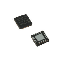
LDS8160-002-T2 IXYS, LDS8160-002-T2 Datasheet - Page 16

LDS8160-002-T2
Manufacturer Part Number
LDS8160-002-T2
Description
IC LED DVR WHT/RGB BCKLGT 16WQFN
Manufacturer
IXYS
Series
LED-Sense™, Power-Lite™r
Type
Backlight, White LED, RGB (I²C Interface)r
Datasheet
1.LDS8160-002-T2.pdf
(39 pages)
Specifications of LDS8160-002-T2
Topology
Linear (LDO), PWM
Number Of Outputs
6
Internal Driver
Yes
Type - Primary
Backlight
Type - Secondary
RGB, White LED
Frequency
1.2MHz
Voltage - Supply
2.3 V ~ 5.5 V
Mounting Type
Surface Mount
Package / Case
16-WQFN, 16-miniQFN
Operating Temperature
-40°C ~ 85°C
Current - Output / Channel
25mA
Internal Switch(s)
Yes
Efficiency
80%
Lead Free Status / RoHS Status
Lead free / RoHS Compliant
Voltage - Output
-
Lead Free Status / Rohs Status
Details
Other names
LDS8160-002-T2-2
LDS8160
Temperature vs. PWM Duty Cycle Profiles
The user must load the PWM correction look up
tables (LUTs) prior to operation. For the LDS8160 all
three tables, LUT-B, LUT-G and LUT-R require
loading (even if using same data for a WLED
application) with the user correction profiles prior to
operation. For RGB applications, LUT-B which drives
LEDA1 And LEDA2 respectively should be assigned
as the Blue color channel. LUT-G which drives
LEDB1 and LEDB2 should be assigned as the Green
color channel, and LUT-R which drives LEDC1 and
LEDC2 should be the RED channel.
The correction tables are based upon LED vendor
characteristics for luminosity vs temperature and
current, LED current de-rating specifications, and
user system thermal design parameters. Figure 7
shows an actual Luminosity vs. Temperature curve of
the NSSM038AT-E RGB LED available from Nichia
Corp.
Figure 8 shows the typical LED characteristic of
decreasing illumination over temperature, but each
color changes differently. This results in white light
color shifts over temperature if not accounted for. It is
typical to see RED LED Luminosity vs Temperature
to change by ± 50% relative to the 25ºC level.
Figure 9 shows that luminosity is linearly dependent
with LED forward currents ≤30 mA. Therefore loss of
LED
compensated for by associated increases in LED
current.
Figure 9 gives the total RGB Power de-rating
specification for the same Nichia NSSM038AT-E
RGB LED. Total power is the combined power (V
I
maximum
exceeding
© 2009 IXYS Corp.
Characteristics subject to change without notice
F
) of each color LED.
Figure 7: Luminosity vs. Temperature curve
(NSSM038AT-E RGB LED from Nichia)
luminosity
RGB
the
LED
maximum
over
power
This curve specifies the
temperature
specified
that
insures
can
junction
not
F
be
x
16
temperature
temperature of 85ºC.
Figure 8: Luminosity vs. LED Forward Current
for Nichia NSSM038AT-E RGB LED
Figure 10 shows the final plot of typical LDS8160
PWM
programmed by the user to adjust for this RGB LED.
This accumulated correction takes into account both
the Luminosity vs Temperature variations and the
adjustments to meet the higher temperature power
de-rating specification.
Given the 5ºC increments of the temperature
adjustment intervals for the LDS8160, the currents
are slowly ramped to equalize loss of light output
before the de-rating profile begins. Once de-rating
begins, the PWM duty cycle is reduced, lowering LED
driver current, to insure meeting and regulating to the
desired maximum operating temperature.
Figure 9: Total power (combined R, G, and B
(NSSM038AT-E RGB LED from Nichia)
LUT
0
diodes) power de-rating curve
with
correction
maximum
profiles
Doc. No. 8160_DS, Rev. N1.0
~ linear from
0 -30 mA
ambient
that
could
operating
be


