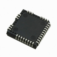
IRS26310DJPBF International Rectifier, IRS26310DJPBF Datasheet - Page 27

IRS26310DJPBF
Manufacturer Part Number
IRS26310DJPBF
Description
IC DRIVER BRIDGE 3-PHASE 44-PLCC
Manufacturer
International Rectifier
Datasheet
1.IRS26310DJTRPBF.pdf
(41 pages)
Specifications of IRS26310DJPBF
Configuration
3 Phase Bridge
Input Type
Non-Inverting
Delay Time
530ns
Current - Peak
200mA
Number Of Configurations
1
Number Of Outputs
3
High Side Voltage - Max (bootstrap)
600V
Voltage - Supply
12 V ~ 20 V
Operating Temperature
-40°C ~ 125°C
Mounting Type
Surface Mount
Package / Case
44-PLCC (32 Leads)
Peak Output Current
200mA
Input Delay
530ns
Output Delay
530ns
Supply Voltage Range
12V To 20V
Driver Case Style
LCC
No. Of Pins
44
Operating Temperature Range
-40°C To +125°C
Rohs Compliant
Yes
Device Type
High Side / Low Side
Family Hvic
General Purpose HVICs
Channels
6
Topology
Three Phase
Application
General Purpose / Motor Control / PDP
Voffset
600
Io+ (ma)
200
Io- (ma)
350
Shutdown / Reset
Yes
Separate Power And Logic Ground
Yes
Integrated Bootstrap Diode
Yes
Over Current Protection
Yes
Uvlo
Vcc / Vbs
Vbsuv+ / Vccuv+ Min (v)
10.4
Vbsuv+ / Vccuv+ Typ (v)
11.1
Vbsuv+ / Vccuv+ Max (v)
11.6
Vbsuv- / Vccuv- Min (v)
10.2
Vbsuv- / Vccuv- Typ (v)
10.9
Dt / Sdt Min (ns)
190
Dt / Sdt Typ (ns)
290
Dt / Sdt Max (ns)
420
T On Min (ns)
400
T On Typ (ns)
530
T On Max (ns)
750
T Off Min (ns)
400
T Off Typ (ns)
530
T Off Max (ns)
750
Fault Reporting
Yes
Package
44 Lead
Part Status
Active & Preferred
Special Features
DC Bus Sensing with Over Voltage Protection
Lead Free Status / RoHS Status
Lead free / RoHS Compliant
Available stocks
Company
Part Number
Manufacturer
Quantity
Price
Company:
Part Number:
IRS26310DJPBF
Manufacturer:
International Rectifier
Quantity:
10 000
Figures 20 and 21 present lab data that illustrates the characteristics of the input filters while receiving ON and OFF
pulses.
The input filter characteristic is shown in Figure 20; the left side illustrates the narrow pulse ON (short positive pulse)
characteristic while the left shows the narrow pulse OFF (short negative pulse) characteristic. The x-axis of Figure
20 shows the duration of PW
duration less than t
also see that once the PW
this interval with the symmetry improving as the duration increases. To ensure proper operation of the HVIC, it is
suggested that the input pulse width for the high-side inputs be ≥ 500 ns.
The difference between the PW
Figure 21; the careful reader will note the scale of the y-axis. The x-axis of Figure 21 shows the duration of PW
while the y-axis shows the resulting PW
of this input filter.
www.irf.com
FIL,IN
, that the resulting PW
IN
duration exceed t
IN
, while the y-axis shows the resulting PW
OUT
and PW
Figure 19: Noise rejecting input filters
Figure 20: Input filter characteristic
OUT
–PW
IN
FIL,IN
OUT
signals of both the narrow ON and narrow OFF cases is shown in
IN
, that the PW
duration. This data illustrates the performance and near symmetry
duration is zero (e.g., the filter rejects the input signal/noise). We
27
OUT
durations mimic the PW
OUT
duration. It can be seen that for a PW
IRS26310DJPbF
© 2008 International Rectifier
IN
durations very well over
IN
IN
,


