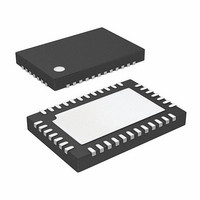
ISL97522IRZ-T Intersil, ISL97522IRZ-T Datasheet - Page 11

ISL97522IRZ-T
Manufacturer Part Number
ISL97522IRZ-T
Description
IC SUPPLY CTRL 4CH TFT-LCD 38QFN
Manufacturer
Intersil
Datasheet
1.ISL97522IRZ-T.pdf
(20 pages)
Specifications of ISL97522IRZ-T
Applications
LCD TV/Monitor
Current - Supply
3mA
Voltage - Supply
4.5 V ~ 13.2 V
Operating Temperature
-40°C ~ 85°C
Mounting Type
Surface Mount
Package / Case
38-QFN
Lead Free Status / RoHS Status
Lead free / RoHS Compliant
The internal current limit circuitry is shown in Figure 16. The
circuit senses the voltage across the R
MOSFET is on; then compare it to the internal voltage
reference to realize the current limit. The internal voltage
reference is generated by a 10mA current and any additional
current set at I
The voltage reference is based on the following equation:
Where V
Where V
Where V
The external resistor R
100K to generate µA of current.
V
I
V
SAD
ISAD
THRESHOLD
=
=
V
---------------- -
ILADJB
ISAD
BE
V
ISAD
R1
REF
CINTB
≈ 0.7V
FBB
is the voltage at pin I
LADJB
=
–
is the voltage at pin I
V
⎛
⎜
⎝
V
----------------------- -
BE
ILADJB
R
–
pin flowing through an 8kΩ resistor.
1
1K I
1
V
should be chosen in the order of
REF
×
COMPARATOR
+
SAD
AMPLIFIER
10μA
11
UVLO
GENERATOR
REFERENCE
GM
⎞
⎟
⎠
FIGURE 15. FUNCTION DIAGRAM OF THE BOOST CONTROLLER
×
SAD
8K
LADJ
DS(ON)
.
COMPENSATION
.
SHUTDOWN
& STARTUP
CONTROL
when the
SLOPE
(EQ. 3)
(EQ. 4)
OSCILLATOR
Σ
ISL97522
CURRENT LIMIT
COMPARATOR
CONTROLLER
AMPLIFIER
CURRENT
LOGIC
PWM
OSC
Hence the maximum output current is determined by the
following equation:
I
Where ΔI
set by:
ΔI
OMAX
L
R
=
1
V
---------
=
L
FIGURE 16. CURRENT LIMIT BLOCK DIAGRAM
IN
⎛
⎜
⎝
L
I
×
LADJB
V
---------------------------------------
GENERATOR
is the peak to peak inductor ripple current, and is
THRESHOLD
---- -
f
D
CURRENT
LIMIT REF
S
BUFFER
V
R
1k
REF
V
DSON
DD
10µA
–
8k
ΔI
--------
2
+
-
L
DRVB
I
I
I
SADJ
SIN
LADJ
⎞
⎠
×
V
---------
V
IN
O
V
CONTROLLER
IN
LOGIC
DRVB
V
December 13, 2006
I
SINB
BOOST
FN7445.0
(EQ. 5)
(EQ. 6)
LX


