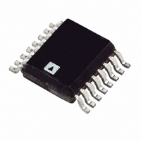
ADT7470ARQZ Analog Devices Inc, ADT7470ARQZ Datasheet - Page 21

ADT7470ARQZ
Manufacturer Part Number
ADT7470ARQZ
Description
IC SENSOR TEMP FAN CTRLR 16QSOP
Manufacturer
Analog Devices Inc
Datasheet
1.ADT7470ARQZ.pdf
(40 pages)
Specifications of ADT7470ARQZ
Function
Fan Control, Temp Monitor
Topology
ADC, Comparator, Fan Speed Control, Register Bank
Sensor Type
External
Sensing Temperature
External Sensor
Output Type
I²C™
Output Alarm
No
Output Fan
Yes
Voltage - Supply
3 V ~ 5.5 V
Operating Temperature
-40°C ~ 125°C
Mounting Type
Surface Mount
Package / Case
16-QSOP
Ic Output Type
Digital
Sensing Accuracy Range
± 12%
Supply Current
500µA
Supply Voltage Range
3V To 5.5V
Sensor Case Style
QSOP
No. Of Pins
16
Msl
MSL 3 - 168 Hours
Termination Type
SMD
Filter Terminals
SMD
Rohs Compliant
Yes
Accuracy %
12%
Lead Free Status / RoHS Status
Lead free / RoHS Compliant
For Use With
EVAL-ADT7470EBZ - BOARD EVALUATION FOR ADT7470
Lead Free Status / RoHS Status
Lead free / RoHS Compliant, Lead free / RoHS Compliant
Available stocks
Company
Part Number
Manufacturer
Quantity
Price
Company:
Part Number:
ADT7470ARQZ
Manufacturer:
AVX
Quantity:
7 600
Part Number:
ADT7470ARQZ
Manufacturer:
ADI/亚德诺
Quantity:
20 000
Part Number:
ADT7470ARQZ-REEL7
Manufacturer:
ADI/亚德诺
Quantity:
20 000
Figure 19 shows a fan drive circuit using an NPN transistor
such as a general-purpose MMBT2222. While these devices
are inexpensive, they tend to have much lower current handling
capabilities and higher on resistance than MOSFETs. When
choosing a transistor, care should be taken to ensure that it
meets the fan’s current requirements. This is the only major
difference between a MOSFET and NPN transistor fan driver
circuit.
When using transistors, ensure that the base resistor is
chosen such that the transistor is fully saturated when the fan
is powered on. Otherwise, there are power inefficiencies in the
implementation.
SETTING THE FAN DRIVE FREQUENCY
Configuration Register 2 Bits[6:4] configure the fan drive
frequency in both high and low frequency drive mode.
ADT7470
Figure 19. Driving a 3-Wire Fan Using an NPN Transistor
TACH/AIN
PWM
4.7kΩ
Low Frequency
10kΩ
3.3V
470Ω
TACH
12V
10kΩ
12V
MMBT2222
12V
FAN
Q1
1N4148
Rev. C | Page 21 of 40
Table 16. Fan Drive Frequency
Register
0x74[6:4]
000
001
010
011
100
101
110
111
INVERTED PWM OUTPUT
The PWM duty cycle can be inverted by writing to the PWM
Configuration registers. If the PWM duty cycle is inverted, then
a PWM duty cycle setting of 33% results in an output duty cycle
of 66%, as the PWM waveform is inverted.
Table 17. PWM1/PWM2 Configuration (Register 0x68)
Bit No.
5
4
Table 18. PWM3/PWM4 Configuration (Register 0x69)
Bit No.
5
4
FAN FULL SPEED FUNCTION
When Pin 13 is configured for full speed operation, pulling the
pin low will cause all fans to run at the maximum PWM duty
cycle. A Logic 1 is output on the PWM pins in this case.
Mnemonic
INV1
INV2
Mnemonic
INV3
INV4
High Frequency Drive
(0x40[6] = 0)
1.4 kHz
22.5 kHz
22.5 kHz
22.5 kHz
22.5 kHz
22.5 kHz
22.5 kHz
22.5 kHz
Description
0 = PWM1 duty cycle not inverted
(default).
1 = PWM1 duty cycle inverted.
0 = PWM2 duty cycle not inverted
(default).
1 = PWM2 duty cycle inverted.
Description
0 = PWM3 duty cycle not inverted
(default).
1 = PWM3 duty cycle inverted.
0 = PWM4 duty cycle not inverted
(default).
1 = PWM4 duty cycle inverted.
Low Frequency Drive
(0x40[6] = 1)
11 Hz
14.7 Hz
22.1 Hz
29.4 Hz
35.3 Hz
44.1 Hz
58.8 Hz
88.2 Hz
ADT7470


