LM87CIMT/NOPB National Semiconductor, LM87CIMT/NOPB Datasheet - Page 21
LM87CIMT/NOPB
Manufacturer Part Number
LM87CIMT/NOPB
Description
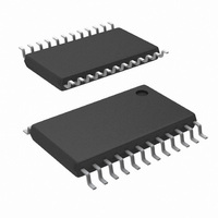
IC INTERFACE SER MONITOR 24TSSOP
Manufacturer
National Semiconductor
Series
PowerWise®r
Datasheet
1.LM87CIMTNOPB.pdf
(34 pages)
Specifications of LM87CIMT/NOPB
Function
Hardware Monitor
Topology
ADC (Sigma Delta), Comparator, Fan Speed Control, Register Bank
Sensor Type
External & Internal
Sensing Temperature
-40°C ~ 125°C, External Sensor
Output Type
I²C™/SMBus™
Output Alarm
No
Output Fan
Yes
Voltage - Supply
2.8 V ~ 3.8 V
Operating Temperature
-40°C ~ 125°C
Mounting Type
Surface Mount
Package / Case
24-TSSOP
Lead Free Status / RoHS Status
Lead free / RoHS Compliant
Other names
*LM87CIMT
*LM87CIMT/NOPB
LM87CIMT
*LM87CIMT/NOPB
LM87CIMT


Reading the Interrupt Status Registers will clear the status bit
and will cause INT# to be deasserted. If the external signal
continues to pull THERM# low, the Interrupt Status Bit will be
reset at the completion of the next conversion cycle. This will
again assert the INT# output. Note that if the external circuitry
pulls THERM# low, but this pin is already low due to the
THERM# output being active, this external signal cannot be
sensed, and the THERM# Interrupt Status Bit will not be set.
Interrupt Status Registers: Reading a Status Register will
return the contents of the Register, and reset the Register. A
subsequent read done before the analog “round-robin” mon-
itoring loop is complete will indicate a cleared Register. Allow
at least 600 ms to allow all Registers to be updated between
reads. In summary, the Interrupt Status Register clears upon
being read, and requires at least 300 ms to be updated. When
the Interrupt Status Register clears, the hardware interrupt
line will also clear until the Registers are updated by the mon-
itoring loop.
Interrupt Status Mirror Registers: The Interrupt Status Mir-
ror Registers provide the same information that the Interrupt
Status Registers do. Reading the Status Mirror Registers,
however, does not reset the status bits.
Interrupt Mask Registers: All sources which are combined
to form the INT# output can be individually masked via the
two Interrupt Mask Registers at 43h, and 44h. The bits in the
mask registers correspond directly to the bits in the Interrupt
Status Registers. Setting an Interrupt Mask bit inhibits that
Interrupt Status Bit from generating an INT# interrupt. Clear-
ing a mask bit allows the corresponding status bit, if set, to
generate INT# outputs. Interrupt Status Bits will be set and
cleared regardless of the state of corresponding Interrupt
Mask Bits, the mask bits merely allow or prevent the status
bits from contributing to the generation of INT# outputs.
Enabling and Clearing INT#: The hardware Interrupt line
(INT#) is enabled by setting the INT#_Enable bit at Bit 1 of
Configuration Register 1. The INT# output can be cleared by
setting the INT#_Clear bit which is Bit 3 of Configuration Reg-
ister 1. When this bit is high, the LM87 monitoring loop will
stop. It will resume when the bit is low.
Thermal Interrupt Mask: In some applications, the user may
want to prevent all thermal error conditions from causing INT#
interrupts. The Thermal INT# Mask bit (Bit 0 of Configuration
Register 2) is provided for this purpose. The THERM# output
discussed later is not affected by the status of the Thermal
INT# Mask bit and will function normally in response to tem-
perature error conditions. If the Thermal INT# Mask bit is set,
the interrupt status for internal and external temperature, the
THERM# input, and the hardware temperature error compar-
isons, will continue to be updated every conversion cycle, but
will not have any effect on the INT# output.
9.2 SMBALERT#
The INT# I/O pin can alternatively be configured as an SM-
BALERT# output in conjunction with the SMBALERT# proto-
col. In this mode of operation, rather than connecting the
INT# /ALERT# pin to the system interrupt inputs, it will be
connected to the SMBALERT# input pin on the SMBus host.
When an INT#/ALERT# type error condition is detected, this
pin will notify the SMBus host that an SMBus device has an
SMBALERT# condition. The SMBus host will then access the
bus using the Alert Response Address (ARA) which is
0001100b. Only the device asserting the SMBALERT# signal
will respond to the ARA, thus providing automatic identifica-
tion of the device generating the SMBALERT#. After acknowl-
edging the slave address, the LM87 will disengage its
SMBALERT# output signal. For more information on the SM-
21
BALERT# protocol, please refer to the System Management
Bus specification. SMBALERT# is enabled by setting Bit 6 of
the Alert Response Enable register at 80h.
9.3 THERM# Interrupts
The THERM# I/O pin is dedicated to temperature related error
conditions. It includes a built in pull-up resistor to minimize
external components. The THERM# Enable bit, Bit 2 of Con-
figuration Register 1 is used to enable the THERM# output.
The THERM# Clear bit, Bit 6 of Configuration Register 1,
when set to 1, clears the THERM# output. TheTHERM# out-
put operates in two different modes when processing thermal
error conditions, Default Mode and ACPI Mode, selected by
the state of the THERM# Interrupt Mode bit at Bit 3 of Con-
figuration Register 2 (0 = Default, 1 = ACPI).
Default Mode:The THERM# ouput operates using a simple
comparison of temperature with the corresponding limit val-
ues. If any temperature value is outside a corresponding limit
in registers 37h, 39h, 2Bh, 38h, 3Ah, or 2Ch, the THERM#
output will go low. The output will remain asserted until it is
reset by: reading Interrupt Status Register 1, by setting the
THERM#CLR bit, or if the temperature falls below the low limit
for that sensor. When THERM# is cleared by reading the sta-
tus register, it may be set again after the next temperature
reading, if the temperature is still above the high limit. When
THERM# is cleared by setting THERM#CLR, it cannot be re-
asserted until this bit is cleared. If THERM# is activated
because a temperature value exceeds one of the hardware
limits in registers 13h, 14h, 17h, or 18h, or exceeds 126 de-
grees C, AOUT will be forced to the full scale value. In this
case, the THERM# output can only be cleared by setting the
THERM#CLR bit or if the temperature returns to 5 degrees
below the hardware limit. Regardless of how THERM# is
cleared, AOUT will be maintained at the full scale value until
the temperature returns to 5 degrees below the hardware limit
that was exceeded.
ACPI Mode: In ACPI mode, THERM# is only activated when
temperatures exceed the high limit settings in registers 13h,
14h, 17h, 18h or the safety limit of 126 degrees C. It will be
de-asserted if the temperature returns at least 5 degrees be-
low the limit. While THERM# is asserted, AOUT will be driven
to full scale to provide maximum cooling from a variable speed
fan.
THERM# also functions as an input. When an external active
low signal is applied to THERM#, it will set the THERM# input
Interrupt Status Bit and will cause AOUT to go to full scale,
regardless of the state of the THERM# Input Interrupt Mask
bit. If the Mask bit is cleared and INT# is enabled, an INT# will
be generated. The THERM# input function is not affected by
the THERM# operating mode.
9.4 Fault Queue
A Fault Queue is incorporated in the external temperature
monitoring sections of the LM87. This serves as a filter to
minimize false triggering caused by short duration or transient
temperature events. The Fault Queue adds a counter be-
tween the comparison logic and the Interrupt Status Register
and THERM# output circuitry. The Fault Queue has a depth
of 3, so three consecutive readings outside of limits is required
to set an external temperature Interrupt Status Bit or generate
a THERM# output. When the monitored temperature is re-
turning within limits, only one conversion within limits is re-
quired to clear the status bit. In other words, the fault queue
is only active when travelling outside of the limits, not when
returning back within limits.
www.national.com
Related parts for LM87CIMT/NOPB
Image
Part Number
Description
Manufacturer
Datasheet
Request
R

Part Number:
Description:
Temperature Sensor IC
Manufacturer:
National Semiconductor
Datasheet:

Part Number:
Description:
National Semiconductor [8-Bit D/A Converter]
Manufacturer:
National Semiconductor
Datasheet:
Part Number:
Description:
National Semiconductor [Media Coprocessor]
Manufacturer:
National Semiconductor
Datasheet:
Part Number:
Description:
Digitally Controlled Tone and Volume Circuit with Stereo Audio Power Amplifier, Microphone Preamp Stage and National 3D Sound
Manufacturer:
National Semiconductor
Datasheet:
Part Number:
Description:
Digitally Controlled Tone and Volume Circuit with Stereo Audio Power Amplifier, Microphone Preamp Stage and National 3D Sound
Manufacturer:
National Semiconductor
Datasheet:
Part Number:
Description:
AC97 Rev 2 Codec with Sample Rate Conversion and National 3D Sound
Manufacturer:
National Semiconductor
Part Number:
Description:
Manufacturer:
National Semiconductor
Datasheet:
Part Number:
Description:
Manufacturer:
National Semiconductor
Datasheet:
Part Number:
Description:
General Purpose, Low Voltage, Low Power, Rail-to-Rail Output Operational Amplifiers
Manufacturer:
National Semiconductor
Datasheet:
Part Number:
Description:
8-bit 20 MSPS flash A/D converter.
Manufacturer:
National Semiconductor
Datasheet:
Part Number:
Description:
Low Noise Quad Operational Amplifier
Manufacturer:
National Semiconductor
Datasheet:
Part Number:
Description:
Quad Differential Line Receivers
Manufacturer:
National Semiconductor
Datasheet:
Part Number:
Description:
Quad High Speed Trapezoidal? Bus Transceiver
Manufacturer:
National Semiconductor
Datasheet:
Part Number:
Description:
Dual Line Receiver
Manufacturer:
National Semiconductor
Datasheet: