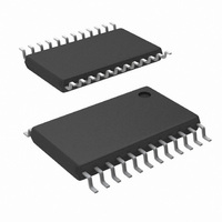
LM87CIMT/NOPB National Semiconductor, LM87CIMT/NOPB Datasheet - Page 28

LM87CIMT/NOPB
Manufacturer Part Number
LM87CIMT/NOPB
Description
IC INTERFACE SER MONITOR 24TSSOP
Manufacturer
National Semiconductor
Series
PowerWise®r
Datasheet
1.LM87CIMTNOPB.pdf
(34 pages)
Specifications of LM87CIMT/NOPB
Function
Hardware Monitor
Topology
ADC (Sigma Delta), Comparator, Fan Speed Control, Register Bank
Sensor Type
External & Internal
Sensing Temperature
-40°C ~ 125°C, External Sensor
Output Type
I²C™/SMBus™
Output Alarm
No
Output Fan
Yes
Voltage - Supply
2.8 V ~ 3.8 V
Operating Temperature
-40°C ~ 125°C
Mounting Type
Surface Mount
Package / Case
24-TSSOP
Lead Free Status / RoHS Status
Lead free / RoHS Compliant
Other names
*LM87CIMT
*LM87CIMT/NOPB
LM87CIMT
*LM87CIMT/NOPB
LM87CIMT
www.national.com
0-3 VID <3:0>
4-5 FAN1 RPM
6-7 FAN2 RPM
1-7 Reserved
2
3
4-5 Reserved
6
Bit
Bit
Bit
Bit
0
0
1
7
0
1
2
3
4
5
13.12 VID0-3/Fan Divisor Register—Address 47h
Power on default – <7:4> is 0101, and <3:0>is mapped to VID
<3:0>
13.13 VID4 Register—Address 49h
Power on default – <7:1> = 100 000, <0> = VID4.
13.14 Configuration Register 2—Address 4Ah
Power on default – <7:0> = 0000 0000 binary
13.15 Interrupt Status Register 1 Mirror—Address 4Ch
Power on default – <7:0> = 0000 0000 binary
Control
Control
VID4
Thermal INT# Mask
Local Temp.
Register Write Once
Bit
Remote Temp.
Register Write Once
Bit
THERM# Interrupt
Mode
IRQ3 Enable
IRQ4 Enable
+2.5Vin
Vccp1
Vcc
+5Vin
Int. Temp.
Ext. Temp.
Name
Name
Name
Name
Read Only
Read Only
Read Only
Read Only
Read Only
Read Only
Read Only
Read Only
Read/Write
Read/Write
Read/Write
Read Only
Read/Write
Read/Write
Read/Write
Once
Read/Write
Once
Read/Write
Read/Write
Read/Write
Read/Write
Read/Write
A one indicates a High or Low limit has been exceeded.
A one indicates a High or Low limit has been exceeded.
A one indicates a High or Low limit has been exceeded.
A one indicates a High or Low limit has been exceeded.
A one indicates a High or Low limit has been exceeded.
A one indicates a High or Low limit has been exceeded.
The VID <3:0> inputs from the Pentium/PRO power supplies that indicate the operating
voltage (e.g. 1.5 V to 2.9 V).
FAN1 Speed Control.
<5:4> = 00 - divide by 1;
<5:4> = 01 - divide by 2;
<5:4> = 10 - divide by 4;
<5:4> = 11 - divide by 8.
FAN2 Speed Control.
<7:6> = 00 - divide by 1;
<7:6> = 01 - divide by 2;
<7:6> = 10 - divide by 4;
<7:6> = 11 - divide by 8.
Bit 4 of VID data from the CPU or power supply that indicates the operating voltage (e.g.
1.5 V to 2.9 V).
When this bit is set to 1, thermal error events will not affect the INT# interrupt output.
THERM# outputs will still function normally.
When set to 1, this bit locks in the value set in the Internal Temp. high limit register at 0x13h.
The value cannot be changed until a power on reset is performed, or the chip is re-Initialized
by writing a 1 to Bit 7 of Configuration Register 1 (Register 40h).
When set to 1, this bit locks in the value set in the External Temp. high limit register at
0x14h. The value cannot be changed until a power on reset is performed, or the chip is re-
Initialized by writing a 1 to Bit 7 of Configuration Register 1 (Register 40h).
When set to 0, the THERM# output functions in Default mode. When set to 1, the THERM#
output functions in ACPI mode.
When set to 1, VID3/IRQ3 is enabled as an active high interrupt input (if the IRQEN bit is
set in bit 7 of the Channel Mode Register).
When set to 1, VID4/IRQ4 is enabled as an active high interrupt input (if the IRQEN bit is
set in bit 7 of the Channel Mode Register).
28
Description
Description
Description
Description


