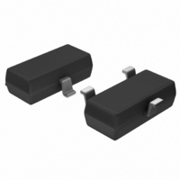
MCP1525T-I/TT Microchip Technology, MCP1525T-I/TT Datasheet - Page 10

MCP1525T-I/TT
Manufacturer Part Number
MCP1525T-I/TT
Description
IC VOLT REF 2.5V SOT23-3
Manufacturer
Microchip Technology
Datasheet
1.MCP1525T-ITT.pdf
(20 pages)
Specifications of MCP1525T-I/TT
Reference Type
Series
Package / Case
SOT-23-3, TO-236-3, Micro3™, SSD3, SST3
Voltage - Output
2.5V
Tolerance
±1%
Temperature Coefficient
50ppm/°C
Voltage - Input
2.7 ~ 5.5 V
Number Of Channels
1
Current - Quiescent
100µA
Current - Output
2mA
Operating Temperature
-40°C ~ 85°C
Mounting Type
Surface Mount
Product
Voltage References
Topology
Series References
Output Voltage
2.5 V
Initial Accuracy
1 %
Average Temperature Coefficient (typ)
50 ppm/C
Series Vref - Input Voltage (max)
7 V
Series Vref - Input Voltage (min)
2.7 V
Shunt Current (max)
8 mA (Typ)
Maximum Operating Temperature
+ 85 C
Input Voltage
5.5 V
Minimum Operating Temperature
- 40 C
Mounting Style
SMD/SMT
Series Vref - Supply Current (max)
100 uA
Lead Free Status / RoHS Status
Lead free / RoHS Compliant
Current - Cathode
-
Lead Free Status / Rohs Status
Lead free / RoHS Compliant
Other names
MCP1525T-I/TT
MCP1525T-I/TTTR
MCP1525TI/TT
MCP1525T-I/TTTR
MCP1525TI/TT
Available stocks
Company
Part Number
Manufacturer
Quantity
Price
Company:
Part Number:
MCP1525T-I/TT
Manufacturer:
LT
Quantity:
3 400
Part Number:
MCP1525T-I/TT
Manufacturer:
MICROCHIP/微芯
Quantity:
20 000
MCP1525/41
4.2
4.2.1
A negative precision voltage reference can be
generated by using the MCP1525 or MCP1541 in the
configuration shown in Figure 4-3.
FIGURE 4-3:
Reference.
In this circuit, the voltage inversion is implemented
using the MCP606 and two equal resistors. The voltage
at the output of the MCP1525 or MCP1541 voltage
reference drives R
input of the MCP606 amplifier. Since the non-inverting
input of the amplifier is biased to ground, the inverting
input will also be close to ground potential. The second
10 k
the amplifier. Since the inverting input of the amplifier is
high-impedance, the current generated through R
also flow through R
voltage of the amplifier is equal to -2.5V for the
MCP1525 and -4.1V for the MCP1541.
DS21653B-page 10
V
DD
resistor is placed around the feedback loop of
V
V
V
Typical Application Circuits
OUT
= 5.0V
SS
IN
MCP1525
MCP1541
NEGATIVE VOLTAGE REFERENCE
V
V
REF
REF
1
= -2.5V, MCP1525
, which is connected to the inverting
= -4.096V, MCP1541
2
C
10 µF
. As a consequence, the output
10 k
0.1%
L
Negative Voltage
R
MCP606
1
V
SS
10 k
= - 5.0V
0.1%
R
2
V
REF
1
will
4.2.2
The MCP1525 and MCP1541 were carefully designed
to provide a voltage reference for Microchip’s 10-bit
and 12-bit families of ADCs. The circuit shown in
Figure 4-4 shows a MCP1541 configured to provide the
reference to the MCP3201, a 12-bit ADC.
FIGURE 4-4:
V
IN
0.1 µF
C
A/D CONVERTER REFERENCE
IN
V
V
V
IN+
IN–
OUT
SS
IN
V
REF
MCP3201
ADC Reference Circuit.
© 2005 Microchip Technology Inc.
10 µF
C
L
3
V
DD
to PICmicro
Microcontroller
0.1 µF
10 µF
= 5.0V
®


