ISL62871HRUZ-T Intersil, ISL62871HRUZ-T Datasheet - Page 10
ISL62871HRUZ-T
Manufacturer Part Number
ISL62871HRUZ-T
Description
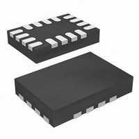
IC CTRLR DC/DC PWM 16-TQFN
Manufacturer
Intersil
Datasheet
1.ISL62871HRUZ-T.pdf
(25 pages)
Specifications of ISL62871HRUZ-T
Pwm Type
Controller
Number Of Outputs
1
Frequency - Max
330kHz
Duty Cycle
100%
Voltage - Supply
3.3 V ~ 25 V
Buck
Yes
Boost
No
Flyback
No
Inverting
No
Doubler
No
Divider
No
Cuk
No
Isolated
No
Operating Temperature
-10°C ~ 100°C
Package / Case
16-UTQFN (16-µTQFN)
Frequency-max
330kHz
Lead Free Status / RoHS Status
Lead free / RoHS Compliant
Available stocks
Company
Part Number
Manufacturer
Quantity
Price

Part Number:
ISL62871HRUZ-T
Manufacturer:
INTERSIL
Quantity:
20 000


BOOT (Pin 18)
Positive input supply for the UGATE high-side MOSFET gate
driver. The BOOT pin is internally connected to the cathode
of the Schottky boot-strap diode. Connect an MLCC
between the BOOT pin and the PHASE pin.
VCC (Pin 19)
Input for the IC bias voltage. Connect +5V to the VCC pin
and decouple with at least a 1µF MLCC to the GND pin. See
“Application Schematics” (Figures 2 and 3) on page 4.
PVCC (Pin 20)
Input for the LGATE and UGATE MOSFET driver circuits.
The PVCC pin is internally connected to the anode of the
Schottky boot-strap diode. Connect +5V to the PVCC pin
and decouple with a 10µF MLCC to the PGND pin. See
“Application Schematics” (Figures 2 and 3) on page 4.
ISL62871 Functional Pin Descriptions
GND (Pin 1)
IC ground for bias supply and signal reference.
EN (Pin 2)
Enable input for the IC. Pulling EN above the V
threshold voltage initializes the soft-start sequence.
VID0 (Pin 3)
Logic input for setpoint voltage selector. Use to select
between the two setpoint reference voltages. External
reference input when enabled by connecting the SET0 pin to
the VCC pin.
SREF (Pin 4)
Soft-start and voltage slew-rate programming capacitor
input. Setpoint reference voltage programming resistor input.
Connects internally to the inverting input of the V
setpoint amplifier. See Figure 9 on page 12 for capacitor and
resistor connections.
SET0 (Pin 5)
Voltage set-point programming resistor input. See Figure 9
on page 12 for resistor connection.
PGOOD (Pin 6)
Power-good open-drain indicator output. This pin changes to
high impedance when the converter is able to supply
regulated voltage. The pull-down resistance between the
PGOOD pin and the GND pin identifies which protective fault
has shut down the regulator. See Table 3 on page 16.
FB (Pin 7)
Voltage feedback sense input. Connects internally to the
inverting input of the control-loop error amplifier. The
converter is in regulation when the voltage at the FB pin
equals the voltage on the SREF pin. The control loop
compensation network connects between the FB pin and the
converter output. See Figure 13 on page 17.
10
ENTHR
SET
ISL62871, ISL62872
voltage
rising
VO (Pin 8)
Output voltage sense input for the R
also serves as the reference input for the overcurrent
detection circuit. See Figure 10 on page 14.
OCSET (Pin 9)
Input for the overcurrent detection circuit. The overcurrent
setpoint programming resistor R
pin to the sense node. See Figure 10 on page 14.
PHASE (Pin 10)
Return current path for the UGATE high-side MOSFET
driver. V
polarity detector input. Connect to junction of output inductor,
high-side MOSFET, and low-side MOSFET. See “Application
Schematics” (Figures 4 and 5) on page 5.
UGATE (Pin 11)
High-side MOSFET gate driver output. Connect to the gate
terminal of the high-side MOSFET of the converter.
BOOT (Pin 12)
Positive input supply for the UGATE high-side MOSFET gate
driver. The BOOT pin is internally connected to the cathode
of the Schottky boot-strap diode. Connect an MLCC
between the BOOT pin and the PHASE pin.
VCC (Pin 13)
Input for the IC bias voltage. Connect +5V to the VCC pin
and decouple with at least a 1µF MLCC to the GND pin. See
“Application Schematics” (Figures 4 and 5) on page 5.
PVCC (Pin 14)
Input for the LGATE and UGATE MOSFET driver circuits.
The PVCC pin is internally connected to the anode of the
Schottky boot-strap diode. Connect +5V to the PVCC pin
and decouple with a 10µF MLCC to the PGND pin. See
“Application Schematics” (Figures 4 and 5) on page 5.
LGATE (Pin 15)
Low-side MOSFET gate driver output. Connect to the gate
terminal of the low-side MOSFET of the converter.
PGND (Pin 16)
Return current path for the LGATE MOSFET driver. Connect
to the source of the low-side MOSFET.
Setpoint Reference Voltage Programming
Voltage identification (VID) pins select user-programmed
setpoint reference voltages that appear at the SREF pin. The
converter is in regulation when the FB pin voltage (V
equals the SREF pin voltage (V
and V
setpoint reference voltages use the naming convention
SREF
IN
sense input for the R
relative to the GND pin, not the PGND pin. The
SREF
3
OCSET
modulator. Inductor current
3
.) The IC measures V
modulator. The VO pin
connects from this
August 14, 2008
FB
FN6707.0
)
FB
Related parts for ISL62871HRUZ-T
Image
Part Number
Description
Manufacturer
Datasheet
Request
R

Part Number:
Description:
Pwm Dc/dc Controller With Vid Inputs For Portable Gpu Core-voltage Regulator
Manufacturer:
Intersil Corporation
Datasheet:
Part Number:
Description:
Intersil Corporation [CMOS Serial Controller Interface]
Manufacturer:
Intersil Corporation
Datasheet:
Part Number:
Description:
Manufacturer:
Intersil Corporation
Datasheet:
Part Number:
Description:
357-036-542-201 CARDEDGE 36POS DL .156 BLK LOPRO
Manufacturer:
Intersil Corporation
Datasheet:
Part Number:
Description:
1024-Word x 4-Bit LSI Static RAM
Manufacturer:
Intersil Corporation
Datasheet:
Part Number:
Description:
General Purpose NPN Transistor Arrays FN341.4
Manufacturer:
Intersil Corporation
Datasheet:
Part Number:
Description:
CMOS 16-Bit Microprocessor
Manufacturer:
Intersil Corporation
Datasheet:
Part Number:
Description:
Manufacturer:
Intersil Corporation
Datasheet:
Part Number:
Description:
Manufacturer:
Intersil Corporation
Datasheet:
Part Number:
Description:
Manufacturer:
Intersil Corporation
Datasheet:
Part Number:
Description:
Manufacturer:
Intersil Corporation
Datasheet:
Part Number:
Description:
CMOS 6-Bit Latch and Decoder Memory Interfaces
Manufacturer:
Intersil Corporation
Datasheet:
Part Number:
Description:
CA3046General Purpose NPN Transistor Arrays
Manufacturer:
Intersil Corporation
Datasheet:
Part Number:
Description:
Manufacturer:
Intersil Corporation
Datasheet:
Part Number:
Description:
TR909 DLC/FLC SLIC with Low Power Standby
Manufacturer:
Intersil Corporation
Datasheet: