LTC1701ES5#TR Linear Technology, LTC1701ES5#TR Datasheet
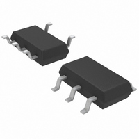
IC CONV DC/DC STEP DOWN TSOT23-5

LTC1701ES5#TR

Manufacturer Part Number
LTC1701ES5#TR
Description
IC CONV DC/DC STEP DOWN TSOT23-5
Manufacturer
Linear Technology
Type
Step-Down (Buck)r
Datasheet

Specifications of LTC1701ES5#TR

Internal Switch(s)
Yes
Synchronous Rectifier
No
Number Of Outputs
1
Voltage - Output
1.25 ~ 5 V
Current - Output
500mA
Frequency - Switching
1MHz
Voltage - Input
2.5 ~ 5.5 V
Operating Temperature
-40°C ~ 85°C
Mounting Type
Surface Mount
Package / Case
TSOT-23-5, TSOT-5, TSOP-5
Lead Free Status / RoHS Status
Contains lead / RoHS non-compliant
Power - Output
-

Available stocks

Company
Part Number
Manufacturer
Quantity
Price
Company:
Part Number:
LTC1701ES5#TRLTC1701ES5
Manufacturer:
LINEAR
Quantity:
5 321
Company:
Part Number:
LTC1701ES5#TRLTC1701ES5
Manufacturer:
LINEAR
Quantity:
105
Company:
Part Number:
LTC1701ES5#TRLTC1701ES5
Manufacturer:
LINEAR/凌特
Quantity:
20 000
Company:
Part Number:
LTC1701ES5#TRLTC1701ES5
Quantity:
5 000
Company:
Part Number:
LTC1701ES5#TR
Manufacturer:
LTC
Quantity:
2 598
FEATURES
APPLICATIO S
TYPICAL
2.5V TO
C1: TAIYO YUDEN JMK316BJ106ML
C2: SANYO POSCAP 6TPA47M
D1: MBRM120L
L1: SUMIDA CD43-4R7
5.5V
Tiny 5-Lead SOT-23 Package
Uses Tiny Capacitors and Inductor
High Frequency Operation: 1MHz
High Output Current: 500mA
Low R
High Efficiency: Up to 94%
Current Mode Operation for Excellent Line
and Load Transient Response
Short-Circuit Protected
Low Quiescent Current: 135 A (LTC1701)
Low Dropout Operation: 100% Duty Cycle
Ultralow Shutdown Current: I
Peak Inductor Current Independent of Inductor Value
Output Voltages from 5V Down to 1.25V
PDAs/Palmtop PCs
Digital Cameras
Cellular Phones
Portable Media Players
PC Cards
Handheld Equipment
10 F
V
IN
C1
+
Figure 1. 2.5V/500mA Step-Down Regulator
DS(ON)
R4
1M
R3
5.1k
APPLICATION
C3
330pF
Internal Switch: 0.28
V
I
TH
IN
U
/RUN
LTC1701
GND
SW
V
FB
Q
U
< 1 A
D1
4.7 H
L1
R2
121k
R1
121k
+
1701 F01a
C2
47 F
V
(2.5V/
500mA)
OUT
DC/DC Converters in SOT-23
DESCRIPTIO
The LTC
step-down, current mode, DC/DC converters. Intended for
low to medium power applications, they operate from 2.5V
to 5.5V input voltage range and switch at 1MHz, allowing
the use of tiny, low cost capacitors and inductors 2mm or
less in height. The output voltage is adjustable from 1.25V
to 5V. A built-in 0.28 switch allows up to 0.5A of output
current at high efficiency. OPTI-LOOP
allows the transient response to be optimized over a wide
range of loads and output capacitors.
The LTC1701 incorporates automatic power saving Burst
Mode
load current drops below the level required for continuous
operation. The LTC1701B operates continuously to very
low load currents to provide low ripple at the expense of
light load efficiency. With no load, the LTC1701 draws only
135 A. In shutdown, both devices draw less than 1 A,
making them ideal for current sensitive applications.
Their small size and switching frequency enables a
0.3 square inches of PC board area.
Burst Mode and OPTI-LOOP are trademarks of Linear Technology Corporation.
complete DC/DC converter function to consume less than
, LTC and LT are registered trademarks of Linear Technology Corporation.
TM
operation to reduce gate charge losses when the
®
1701/LTC1701B are the industry’s first SOT-23
100
95
90
85
80
75
70
65
60
55
50
1
V
V
LTC1701/LTC1701B
LTC1701
IN
OUT
LTC1701B
U
1MHz Step-Down
= 3.3V
= 2.5V
Efficiency Curve
LOAD CURRENT (mA)
10
100
TM
compensation
1701 F01b
1000
1

Related parts for LTC1701ES5#TR

LTC1701ES5#TR Summary of contents

Page 1

... Their small size and switching frequency enables a complete DC/DC converter function to consume less than 0.3 square inches of PC board area. , LTC and LT are registered trademarks of Linear Technology Corporation. Burst Mode and OPTI-LOOP are trademarks of Linear Technology Corporation. L1 4.7 H ...

Page 2

LTC1701/LTC1701B ABSOLUTE AXI U RATI GS (Note 1) (Voltages Referred to GND Pin) V Voltage (Pin 5).......................................– 0. /RUN Voltage (Pin 4) ..............................– 0. Voltage (Pin 3) ......................................– 0.3V ...

Page 3

W U TYPICAL PERFORMANCE CHARACTERISTICS Efficiency vs Load Current 100 V = 2.5V OUT LTC1701 LTC1701B 100 1000 LOAD CURRENT (mA) 1701 • G01 ...

Page 4

LTC1701/LTC1701B CTIO S SW (Pin 1): The Switch Node Connection to the Inductor. This pin swings from Schottky diode (external) IN voltage drop below ground. The cathode of the Schottky diode must ...

Page 5

U OPERATIO The LTC1701 uses a contant off-time, current mode archi- tecture. The operating frequency is then determined by the off-time and the difference between V The output voltage is set by an external divider returned to the V pin. ...

Page 6

LTC1701/LTC1701B U U APPLICATIO S I FOR ATIO Accepting larger values of I allows the use of low L inductances, but results in higher output voltage ripple and greater core losses. A reasonable starting point for setting ripple current is ...

Page 7

U U APPLICATIO S I FOR ATIO Input Capacitor (C ) Selection IN In continuous mode, the input current of the converter is a square wave with a duty cycle of approximately prevent large voltage transients, ...

Page 8

LTC1701/LTC1701B U U APPLICATIO S I FOR ATIO Figure 2. The output voltage is set by a resistive divider according to the following formula 1.25V(1 + R2/R1) OUT To prevent stray pickup, a capacitor of about 5pF can ...

Page 9

U U APPLICATIO S I FOR ATIO During normal operation the voltage on the I will vary from 1.25V to 2.25V depending on the load current. Pulling the I /RUN pin below 0.8V puts the TH LTC1701 into a low ...

Page 10

LTC1701/LTC1701B U U APPLICATIO S I FOR ATIO The following table lists thermal resistance for several different board sizes and copper areas. All measurements were taken in still air on 3/32" FR-4 board with one ounce copper. Table 1. Measured ...

Page 11

... C2: AVX TAJA226M006R C4, C5: TAIYO YUDEN LMK212BJ105MG Information furnished by Linear Technology Corporation is believed to be accurate and reliable. However, no responsibility is assumed for its use. Linear Technology Corporation makes no represen- tation that the interconnection of its circuits as described herein will not infringe on existing patent rights ...

Page 12

... Up to 500mA IN OUT SO-8, 2.95V V 10V, V Output IN REF 8-Pin MSOP and SO Packages Q 550kHz, 6-Pin SOT-23 5A, 2.2V < V OUT 2.65 V 10V, MSOP Package 600mA Q IN 95% Efficiency MSOP Package 600mA Q 1701Bfa LT/TP 1100 REV A 2K • PRINTED IN USA LINEAR TECHNOLOGY CORPORATION 1999 < 10V IN ...

Related keywords