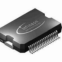
TLE6361G Infineon Technologies, TLE6361G Datasheet - Page 51

TLE6361G
Manufacturer Part Number
TLE6361G
Description
IC PS SYSTEM MULTI VOLT PDSO-36
Manufacturer
Infineon Technologies
Type
Step-Down (Buck)r
Datasheet
1.TLE6361G.pdf
(57 pages)
Specifications of TLE6361G
Internal Switch(s)
Yes
Synchronous Rectifier
No
Number Of Outputs
4
Voltage - Output
5.4 ~ 6.05 V
Current - Output
1.5A
Frequency - Switching
370kHz
Voltage - Input
5.5 ~ 60 V
Operating Temperature
-40°C ~ 150°C
Mounting Type
Surface Mount
Package / Case
DSO-36
Output Voltage
5.5 V
Output Current
1.5 A
Input Voltage Max
60 V
Maximum Operating Temperature
+ 150 C
Minimum Operating Temperature
- 40 C
Mounting Style
SMD/SMT
Operating Temperature Range
- 40 C to + 150 C
Output Voltage Tolerance
+/- 10 %
Lead Free Status / RoHS Status
Contains lead / RoHS non-compliant
Power - Output
-
Lead Free Status / Rohs Status
Lead free / RoHS Compliant
Other names
SP000013297
TLE6361GNT
TLE6361GT
TLE6361GNT
TLE6361GT
Available stocks
Company
Part Number
Manufacturer
Quantity
Price
Company:
Part Number:
TLE6361G
Manufacturer:
INFINEON
Quantity:
5 510
Part Number:
TLE6361G
Manufacturer:
INFINEON/英飞凌
Quantity:
20 000
5.2.2
The choice of the output capacitor effects straight to the minimum achievable ripple
which is seen at the output of the buck converter. In continuous conduction mode the
ripple of the output voltage equals:
From the formula it is recognized that the ESR has a big influence in the total ripple at
the output, so ceramic types or low ESR tantalum capacitors are recommended for the
application.
One other important thing to note are the requirements for the resonant frequency of the
output LC-combination. The choice of the components L and C have to meet also the
specified range given in section 3.3 otherwise instabilities of the regulation loop might
occur.
5.2.3
At high load currents, where the current through the inductance flows continuously, the
input capacitor is exposed to a square wave current with its duty cycle V
prevent a high ripple to the battery line a capacitor with low ESR should be used. The
maximum RMS current which the capacitor has to withstand is calculated to:
5.2.4
For lowest power loss in the freewheeling path Schottky diodes are recommended. With
those types the reverse recovery charge is negligible and a fast handover from
freewheeling to forward conduction mode is possible. Depending on the application (12V
battery systems) 40V types could be also used instead of the 60V diodes.
A fast recovery diode with recovery times in the range of 30ns can be also used if smaller
junction capacitance values (smaller spikes) are desired, the slew resistor should be set
in this case between 10 and 20k .
Data Sheet, Rev. 2.0
Buck output capacitor (C
Input capacitor (C
Freewheeling diode / catch diode (D
I
RMS
V
Ripple
=
I2
) selection:
I
LOAD
=
B
) selection:
I
V
--------------
V
R
OUT
IN
ESRCB
51
B
1
)
+
+
----------------------------
8 f
1
-- -
3
SW
---------------------- -
2 I
1
C
LOAD
I
B
2
TLE 6361 G
2005-03-01
OUT
/V
I
. To


