MT9HTF6472AY-800D1 Micron Technology Inc, MT9HTF6472AY-800D1 Datasheet - Page 12
MT9HTF6472AY-800D1
Manufacturer Part Number
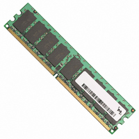
MT9HTF6472AY-800D1
Description
MODULE DDR2 512MB 240-DIMM
Manufacturer
Micron Technology Inc
Datasheet
1.MT9HTF12872AY-40ED1.pdf
(44 pages)
Specifications of MT9HTF6472AY-800D1
Memory Type
DDR2 SDRAM
Memory Size
512MB
Speed
800MT/s
Package / Case
240-DIMM
Lead Free Status / RoHS Status
Lead free / RoHS Compliant


Figure 4:
pdf: 09005aef80e6f860, source: 09005aef80e5b799
HTF9C32_64_128x72AG_2.fm - Rev. C 6/05 EN
COMMAND
ADDRESS
DQS
V
DM
ODT
DQ
V
CK#
CKE
V
V
V
DD
DDL
CK
Rtt
TT
REF
DD
9
Q
7
7
1
7
LOW LEVEL
LVCMOS
DON’T CARE
High-Z
High-Z
High-Z
t
VTD
1
T0
8
LOW LEVEL
t
SSTL_18
CL
Power-up:
V
clock (CK, CK#)
DD
t
DDR2 Power-Up and Initialization
CK
and stable
T = 200µs (min)
Indicates a break in
time scale
t
CL
8
Notes: 1. V
NOP 2
Ta0
T = 400ns (min)
10. A10 should be HIGH at states Tb0 and Tg0 to ensure a PRECHARGE (all banks) command is
11. Bits E7, E8, and E9 must be set to 1 to set OCD default.
12. Bits E7, E8, and E9 must be set to 0 to set OCD exit and all other operating parameters of
2. Apply V
3. Either a NOP or DESELECT command may be applied.
4. 200 cycles of clock (CK, CK#) are required before a READ command can be issued. CKE
5. Two or more REFRESH commands are required.
6. Bits E7, E8, and E9 must all be set to 0 with all other operating parameters of EMRS set as
7. PRE = PRECHARGE command, LM = LOAD MODE command, REF = REFRESH command, ACT
8. DM represents all DM. DQS represents all DQS, DQS#, RDQS,and RDQS# (RDQS/RDQS# only
9. CKE pin uses LVCMOS input levels prior to state T0. After state T0, CKE pin uses SSTL_18
256MB, 512MB, 1GB (x72, SR, ECC) 240-Pin DDR2 SDRAM UDIMM
zero to avoid device latch-up.
The time from when V
to or less than 20ms. One of the following two conditions (a or b) MUST be met:
any V
must be HIGH the entire time.
required.
= ACTIVE command, RA = Row Address, BA = Bank Address.
functional on RDIMMs using x8 components). DQ represents all DQ.
input levels.
issued.
EMRS set as required.
A10 = 1
A.
Tb0
B.
PRE
TT
is not applied directly to the device; however,
t
RPA
DD
V
V
V
Apply V
Apply V
DD
TT
REF
EMR(2)
DD
CODE
supply can not exceed 0.3V.
Tc0
LM
, V
may be 0.95V maximum during power up.
Q before or at the same time as V
tracks V
t MRD
DD
DD
DD
L, and V
EMR(3)
L before or at the same time as V
CODE
Td0
LM
before or at the same time as V
DD
t MRD
Q/2.
DLL Enable
DD
DD
EMR with
CODE
Te0
LM
first starts to power-up to the completion of V
Q are driven from a single power converter output.
t MRD
12
5
DLL Reset
MR with
CODE
Tf0
LM
t MRD
Micron Technology, Inc., reserves the right to change products or specifications without notice.
A10 = 1
Tg0
PRE
t
RPA
TT
200 cycles of CK
and V
Th0
REF
DD
DD
t RFC
t
VTD should be greater than or equal to
L.
Q.
3
REF
See note 4
REF
Ti0
. The voltage difference between
©2003, 2004, 2005 Micron Technology, Inc. All rights reserved.
t RFC
DLL Reset
MR w/o
CODE
Tj0
LM
t MRD
OCD Default 10
EMR with
CODE
Tk0
LM
DD
Initialization
Q must be equal
t MRD
OCD Exit 11
EMR with
CODE
LM
Tl0
t MRD
Operation
Normal
VALID
VALID 3
Tm0
See
note
3
Related parts for MT9HTF6472AY-800D1
Image
Part Number
Description
Manufacturer
Datasheet
Request
R

Part Number:
Description:
IC SDRAM 64MBIT 133MHZ 54TSOP
Manufacturer:
Micron Technology Inc
Datasheet:

Part Number:
Description:
IC SDRAM 64MBIT 5.5NS 86TSOP
Manufacturer:
Micron Technology Inc
Datasheet:
Part Number:
Description:
IC SDRAM 64MBIT 200MHZ 86TSOP
Manufacturer:
Micron Technology Inc
Datasheet:
Part Number:
Description:
IC SDRAM 64MBIT 133MHZ 54TSOP
Manufacturer:
Micron Technology Inc
Datasheet:
Part Number:
Description:
IC SDRAM 128MBIT 133MHZ 54TSOP
Manufacturer:
Micron Technology Inc
Datasheet:

Part Number:
Description:
IC SDRAM 256MBIT 133MHZ 90VFBGA
Manufacturer:
Micron Technology Inc
Datasheet:
Part Number:
Description:
IC SDRAM 128MBIT 133MHZ 54TSOP
Manufacturer:
Micron Technology Inc
Datasheet:
Part Number:
Description:
IC SDRAM 256MBIT 133MHZ 54TSOP
Manufacturer:
Micron Technology Inc
Datasheet:

Part Number:
Description:
IC DDR SDRAM 512MBIT 6NS 66TSOP
Manufacturer:
Micron Technology Inc
Datasheet:
Part Number:
Description:
IC SDRAM 128MBIT 167MHZ 86TSOP
Manufacturer:
Micron Technology Inc
Datasheet:
Part Number:
Description:
IC SDRAM 128MBIT 143MHZ 86TSOP
Manufacturer:
Micron Technology Inc
Datasheet:

Part Number:
Description:
SDRAM 256M-BIT 1.8V 54-PIN VFBGA
Manufacturer:
Micron Technology Inc
Datasheet:
Part Number:
Description:
IC SDRAM 128MBIT 143MHZ 86TSOP
Manufacturer:
Micron Technology Inc
Datasheet:

Part Number:
Description:
IC SDRAM 128MBIT 125MHZ 54VFBGA
Manufacturer:
Micron Technology Inc
Datasheet:
Part Number:
Description:
IC SDRAM 128MBIT 125MHZ 54VFBGA
Manufacturer:
Micron Technology Inc
Datasheet: