ZUP36-12/U TDK Corporation, ZUP36-12/U Datasheet - Page 18
ZUP36-12/U
Manufacturer Part Number
ZUP36-12/U
Description
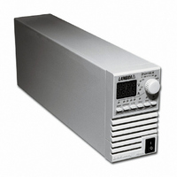
PWR SUP BENCH PROG 0-36V 432W
Manufacturer
TDK Corporation
Series
ZUPr
Type
Enclosedr
Specifications of ZUP36-12/U
Number Of Outputs
1
Efficiency
84%
Voltage - Output
0 ~ 36V
Power (watts)
432W
Applications
Commercial
Power Supply Type
Switching (Closed Frame)
Voltage - Input
85 ~ 265VAC
Mounting Type
Chassis Mount
1st Output
0 ~ 36 VDC @ 12A
Size / Dimension
13.78" L x 4.88" W x 2.76" H (350mm x 124mm x 70mm)
Power (watts) - Rated
432W
Operating Temperature
0°C ~ 50°C
Approvals
CE, EN, UL
Line Regulation
0.01%
Load Regulation
0.01%
Output Current (max)
12A
Input Voltage
85 to 265V
Input Frequency
47 to 63Hz
Screening Level
Commercial
Operating Temperature Min Deg. C
0C
Operating Temperature Max Deg. C
50C
Mounting Style
Desktop
Accuracy
0.02% + 20 mV
Brand/series
ZUP
Current, Output
12 A
Display Type
Digital Meter
Power, Output
432 W
Power, Rating
432 W (Max.)
Regulation, Line
0.01% + 2 mA⁄1 mV + 0.005%
Regulation, Load
0.01% + 5 mA⁄2 mV + 0.005%
Standards
UL Listed, CE Marked
Temperature Coefficient
30 ppm⁄°C (CV)⁄100 ppm⁄°C (CC)
Temperature, Operating, Maximum
50 °C
Temperature, Operating, Minimum
0 °C
Voltage, Input
85-265 VAC
Voltage, Noise
50 mV @ 20 MHz BW
Voltage, Output
36 VDC
Voltage, Ripple
5 mV @ 5 Hz to 1 MHz
Lead Free Status / RoHS Status
Lead free / RoHS Compliant
3rd Output
-
2nd Output
-
4th Output
-
Lead Free Status / Rohs Status
RoHS Compliant part
Other names
285-1676
ZUP3612/U
ZUP3612/U


3.1
This chapter contains instructions for initial inspection, preparation for use and repackaging for
shipment. Connection to PC, linking ZUP units and setting the address are described in chapter 5.
3.2 INITIAL INSPECTION
3.2.1 Mechanical inspection
3.2.2 Preparation for use
3.3 AC SOURCE REQUIREMENTS
3.4 COOLING & PLACEMENT
3.5 RACK MOUNTING
3.6 POWER CONNECTION
Prior to shipment this power supply was inspected and found free of mechanical or electrical defects.
Upon unpacking of the power supply, inspect for any damage which may have occurred in transit. Keep
all packing materials until inspection has been completed. If any damage is detected, file a claim with
the carrier immediately and notify the Nemic-Lambda sales or service facility nearest you.
The mechanical inspection should confirm that there is no exterior damage to the power supply such as
broken knobs or connectors and that the front panel and meter face are not scratched or cracked.
In order to be operational the power supply must be connected to an appropriate AC source. The line
voltage must be within the power supply specification. DO NOT apply power before reading paragraph
3.3.
The ZUP series can be operated from a nominal 100V to 240V, single phase, 47 ~ 63Hz. The input
voltage range and current required for each model is specified in chapter 2. Make sure that under
heavy load, the AC voltage supplied to the power supply does not fall below “low limit” specifications.
This power supply is fan cooled. Upon installation ensure sufficient space for air intake (front panel) and
exhaust (rear panel). The power supply should be used in an area where the ambient temperature
does not exceed +50 C
ZUP models can be mounted in a standard 19” rack (3U height). The 200W and 400W models occupy
1/6 rack length. The 800W model occupies 1/3 rack length. The power supplies should be fixed by M4
screws replacing the rubber feet on the bottom of the power supply. The screws must not protrude more
than 6mm into the power supply. Refer to the outline drawing in this chapter for mounting details.
CHAPTER 3 INSTALLATION
GENERAL
operation of other instruments. If your equipment is susceptible to magnetic fields,
ZUP series power supplies generate a magnetic field which might affect the
Connection of this power supply to an AC power source should
O
be made by an electrician or other qualified personnel.
do not position adjacent to the ZUP.
CAUTION
NOTE
Related parts for ZUP36-12/U
Image
Part Number
Description
Manufacturer
Datasheet
Request
R

Part Number:
Description:
PWR SUP BENCH PROG 0-36V 216W
Manufacturer:
TDK Corporation
Datasheet:
Part Number:
Description:
PWR SUP BENCH PROG 0-36V 864W
Manufacturer:
TDK Corporation
Datasheet:

Part Number:
Description:
POWER SUPPLY, 864W POWER, W/ OUTPUT BANANA JACKS AND US LINE
Manufacturer:
TDK Corporation
Part Number:
Description:
TDK DC to DC Converters, DC to AC Inverters
Manufacturer:
TDK Corporation
Datasheet:
Part Number:
Description:
TDK DC to DC Converters, DC to AC Inverters
Manufacturer:
TDK Corporation
Datasheet: