ZUP10-40/U TDK Corporation, ZUP10-40/U Datasheet - Page 4
ZUP10-40/U
Manufacturer Part Number
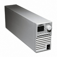
ZUP10-40/U
Description
PWR SUP BENCH PROG 0-10V 400W
Manufacturer
TDK Corporation
Series
ZUPr
Type
Programmabler
Specifications of ZUP10-40/U
Load Regulation
0.01%
Voltage - Output
0 ~ 10V
Number Of Outputs
1
Power (watts)
400W
Applications
Commercial
Power Supply Type
Switching (Closed Frame)
Voltage - Input
85 ~ 265VAC
Mounting Type
Chassis Mount
1st Output
0 ~ 10 VDC @ 40A
Size / Dimension
13.78" L x 4.88" W x 2.76" H (350mm x 124mm x 70mm)
Power (watts) - Rated
400W
Operating Temperature
0°C ~ 50°C
Efficiency
82%
Approvals
CE, EN, UL
Line Regulation
0.01%
Power Supply Output Type
Variable
No. Of Outputs
1
Output Voltage
10V
Output Current
40A
Power Rating
400W
Input Voltage
85V AC To 265V AC
Length
350mm
Width
70mm
Accuracy
0.02% + 8 mV
Brand/series
ZUP
Current, Output
40 A
Display Type
Digital Meter
Power, Output
400 W
Power, Rating
400 W (Max.)
Regulation, Line
0.01% + 2 mA⁄1 mV + 0.005%
Regulation, Load
0.01% + 5 mA⁄2 mV + 0.005%
Standards
UL Listed, CE Marked
Temperature Coefficient
30 ppm⁄°C (CV)⁄100 ppm⁄°C (CC)
Temperature, Operating, Maximum
50 °C
Temperature, Operating, Minimum
0 °C
Voltage, Input
85-265 VAC
Voltage, Noise
50 mV @ 20 MHz BW
Voltage, Output
10 VDC
Voltage, Ripple
5 mV @ 5 Hz to 1 MHz
Lead Free Status / RoHS Status
Lead free / RoHS Compliant
3rd Output
-
2nd Output
-
4th Output
-
Lead Free Status / Rohs Status
RoHS Compliant part
Other names
285-1669
ZUP1040/U
ZUP1040/U


TABLE OF CONTENTS: ZUP SERIES
WARRANTY ..........................................................................................
SAFETY INSTRUCTIONS .....................................................................
CHAPTER 1. General Information
CHAPTER 2. Specifications
CHAPTER 3. Installation
1.1 User manual content
1.2 Introduction
1.3 Accessories
2.1 200W/400W Series
2.2 Supplemental characteristics .........................................................
3.1 General
3.2 Initial inspection
3.3 AC source requirements
3.4 Cooling and placement
3.5 Rack mounting
3.6 Power connection
3.7 Connecting the load .......................................................................
3.8 External control connector
3.9 Repackaging for shipment
1.2.1 General description
1.2.2 Configurations
1.2.3 Control via the serial communication port
1.2.4 Output connections
1.2.5 Analog voltage programming
1.2.6 Parallel operation
1.2.7 Cooling and mechanical construction .....................................
1.3.1 General
1.3.2 Serial link cables
1.3.3 AC cables
1.3.4 Front panel outputs option
3.2.1 Mechanical inspection
3.2.2 Preparation for use
3.7.1 Selecting wire size
3.7.2 Wire termination .....................................................................
3.7.3 Single load connection, local sense
3.7.4 Single load connection, remote sensing ................................
3.7.5 Multiple load connections, radial distribution method
3.7.6 Multiple load connections with distribution terminals .............
3.7.7 Grounding outputs
3.8.1 General
3.8.2 Pin description .......................................................................
3.8.3 Technical description
3.8.4 Default connections................................................................
800W Series...................................................................................
.....................................................................
................................................................
......................................................
pg. 1
pg. 2
pg. 5
pg. 7
pg. 9
pg. 6
pg. 11
pg. 12
pg.13
pg.14
pg.15
pg.16
pg.17
pg.18
Related parts for ZUP10-40/U
Image
Part Number
Description
Manufacturer
Datasheet
Request
R

Part Number:
Description:
PWR SUP BENCH PROG 0-10V 200W
Manufacturer:
TDK Corporation
Datasheet:
Part Number:
Description:
PWR SUP BENCH PROG 0-10V 800W
Manufacturer:
TDK Corporation
Datasheet:

Part Number:
Description:
TDK DC to DC Converters, DC to AC Inverters
Manufacturer:
TDK Corporation
Datasheet:
Part Number:
Description:
TDK DC to DC Converters, DC to AC Inverters
Manufacturer:
TDK Corporation
Datasheet: