28029 Parallax Inc, 28029 Datasheet - Page 133
28029
Manufacturer Part Number
28029
Description
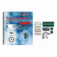
KIT PARTS SMART SENSORS W/TEXT
Manufacturer
Parallax Inc
Datasheet
1.122-28029.pdf
(340 pages)
Specifications of 28029
Accessory Type
Parts Kit
Product
Microcontroller Accessories
Lead Free Status / RoHS Status
Contains lead / RoHS non-compliant
For Use With/related Products
BASIC Stamp® or Javelin Modules
Lead Free Status / RoHS Status
Lead free / RoHS Compliant, Contains lead / RoHS non-compliant
Other names
28029PAR


Chapter 4: Hitachi HM55B Compass Module · Page 121
Schematic and Wiring Diagram
The HM55B can be connected with its Dout and Din pins tied together so that they
transmit and receive signals to and from the same BASIC Stamp I/O pin. Another
BASIC Stamp I/O pin is connected to the device's clock (CLK) pin. The BASIC Stamp
will send pulses to this pin as it makes the chip send its status or measurements or receive
commands. The BASIC Stamp also sends low signals to the Compass Module's /Enable
pin before it exchanges any data, and also to initialize each magnetic field measurement.
√
Build the circuit shown in Figure 4-3.
Figure 4-3: Compass Module Schematic and Wiring Diagram
Testing the Compass Module
This example program tests to make sure the compass module is connected properly and
in working order.
There may be sizeable differences between the magnetic north
reported by a mechanical compass and the one reported by the compass module. After
the calibration programs in upcoming activities, all apparent measurement errors should
disappear.
Figure 4-4 shows what the compass should display when it detects that it is facing 35°
clockwise of north. Again, don't worry about exact direction at this point because the
program is only testing to make sure the module is working. So long as you can use it to
get a general idea of north, south, east and west, it's in working order.
Related parts for 28029
Image
Part Number
Description
Manufacturer
Datasheet
Request
R


Part Number:
Description:
Microcontroller Modules & Accessories DISCONTINUED BY PARALLAX
Manufacturer:
Parallax Inc

Part Number:
Description:
BOOK UNDERSTANDING SIGNALS
Manufacturer:
Parallax Inc
Datasheet:


Part Number:
Description:
COMPETITION RING FOR SUMOBOT
Manufacturer:
Parallax Inc
Datasheet:


Part Number:
Description:
TEXT INFRARED REMOTE FOR BOE-BOT
Manufacturer:
Parallax Inc
Datasheet:
Part Number:
Description:
BOARD EXPERIMENT+LCD NX-1000
Manufacturer:
Parallax Inc
Datasheet:

Part Number:
Description:
CONTROLLER 16SERVO MOTOR CONTROL
Manufacturer:
Parallax Inc
Datasheet:

Part Number:
Description:
BASIC STAMP LOGIC ANALYZER
Manufacturer:
Parallax Inc
Datasheet:

Part Number:
Description:
IC MCU 2K FLASH 50MHZ SO-18
Manufacturer:
Parallax Inc
Datasheet: