28029 Parallax Inc, 28029 Datasheet - Page 67
28029
Manufacturer Part Number
28029
Description
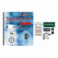
KIT PARTS SMART SENSORS W/TEXT
Manufacturer
Parallax Inc
Datasheet
1.122-28029.pdf
(340 pages)
Specifications of 28029
Accessory Type
Parts Kit
Product
Microcontroller Accessories
Lead Free Status / RoHS Status
Contains lead / RoHS non-compliant
For Use With/related Products
BASIC Stamp® or Javelin Modules
Lead Free Status / RoHS Status
Lead free / RoHS Compliant, Contains lead / RoHS non-compliant
Other names
28029PAR


√
√
√
√
Plug the Parallax Serial LCD into the breadboard as shown in Figure 2-11 on
page 56.
Plug one end of the extension cable into the 3-pin header, making sure the white,
red, and black wires are oriented as shown. The black wire should be connected
to Vss, the Red wire to Vdd, and the white wire to P15.
Connect the other end of the cable so that the black wire is connected to the
Ping)))'s GND pin, the red wire is connected to the 5 V pin, and the white wire is
connected to the RX pin. Double-check all your connections, including your
jumper setting, and make sure they are correct.
Reconnect power to your board.
WARNING!
connections are correct.
Parallax Serial LCD could be permanently damaged.
Do not connect power to your board until you are positive the
If you make a mistake with the LCD connections, the
Chapter 2: The Ping))) Ultrasonic Sensor · Page 55
Figure 2-10
Breadboard Wiring for Ping)))
Sensor Cable Connection
Related parts for 28029
Image
Part Number
Description
Manufacturer
Datasheet
Request
R


Part Number:
Description:
Microcontroller Modules & Accessories DISCONTINUED BY PARALLAX
Manufacturer:
Parallax Inc

Part Number:
Description:
BOOK UNDERSTANDING SIGNALS
Manufacturer:
Parallax Inc
Datasheet:


Part Number:
Description:
COMPETITION RING FOR SUMOBOT
Manufacturer:
Parallax Inc
Datasheet:


Part Number:
Description:
TEXT INFRARED REMOTE FOR BOE-BOT
Manufacturer:
Parallax Inc
Datasheet:
Part Number:
Description:
BOARD EXPERIMENT+LCD NX-1000
Manufacturer:
Parallax Inc
Datasheet:

Part Number:
Description:
CONTROLLER 16SERVO MOTOR CONTROL
Manufacturer:
Parallax Inc
Datasheet:

Part Number:
Description:
BASIC STAMP LOGIC ANALYZER
Manufacturer:
Parallax Inc
Datasheet:

Part Number:
Description:
IC MCU 2K FLASH 50MHZ SO-18
Manufacturer:
Parallax Inc
Datasheet: