AT89STK-06 Atmel, AT89STK-06 Datasheet - Page 10
AT89STK-06
Manufacturer Part Number
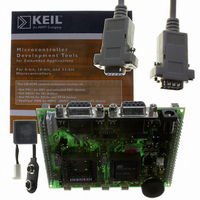
AT89STK-06
Description
KIT DEMOBOARD 8051 MCU W/CAN
Manufacturer
Atmel
Datasheet
1.AT89STK-06.pdf
(22 pages)
Specifications of AT89STK-06
Main Purpose
Interface, CAN
Embedded
*
Utilized Ic / Part
T89C51CC01/CC02, AT89C51CC03
Primary Attributes
*
Secondary Attributes
*
Lead Free Status / RoHS Status
Contains lead / RoHS non-compliant


4339C–CAN–07/05
Hardware Description
2.5.2
Table 2-2. Table of Solder Strap
2.5.2.1
2-8
SP1
SP2
SP3
Reference
Solder straps
T89C51CC02/T89C5115
Support (SP1)
CC02 & C5115
mode
X2_44
X2_52
PCB Name
Solder straps allow to modify the board configuration for specific usage such as
T89C51CC02 compatibility.
Figure 2-11. Solder Strap definition
When using T89C51CC02 or T89C5115 products with the AT89STK-06 board ( see
¨PLCC adapter for T89C51CC02 user guide: CANADAPT28), the SP1 solder pad
should be closed to ensure correct hardware conditions setting on P1.0 port.
SP1 solder pad connects ISP push button to P1.0 microcontroller port and the
CANADAPT28 adapter should be inseted in U2 (PLCC44) socket.
Figure 2-12. AT89STK-06 Board with CANADAPT28
For T89C51CC02 usage, allows to redirect the ISP signal to P1.0, for
hardware conditions.
Connect PLCC44 Xtal2 to XTAL2 of the generic extension board (optionnal)
Connect PLCC52 Xtal2 to XTAL2 of the generic extension board (optionnal)
Solder Pad
Comments (guidelines)
“Open”
Solder gout
AT89STK-06 Demo Board Software Demo Guide
“Close”
Open
Open
Open
Default
Related parts for AT89STK-06
Image
Part Number
Description
Manufacturer
Datasheet
Request
R

Part Number:
Description:
KIT EVAL APPL MASS STORAGE
Manufacturer:
Atmel
Datasheet:

Part Number:
Description:
KIT STARTER FOR AT89C5131
Manufacturer:
Atmel
Datasheet:

Part Number:
Description:
KIT STARTER FOR AT83C24
Manufacturer:
Atmel
Datasheet:

Part Number:
Description:
EVAL BOARD FOR AT83C26
Manufacturer:
Atmel
Datasheet:

Part Number:
Description:
KIT STARTER FOR MCU AT8XC5122/23
Manufacturer:
Atmel
Datasheet:

Part Number:
Description:
KIT STARTER FOR AT89C51RX2
Manufacturer:
Atmel
Datasheet:


Part Number:
Description:
8-Bit Microcontroller with 4K Bytes Flash
Manufacturer:
ATMEL Corporation
Datasheet:

Part Number:
Description:
DEV KIT FOR AVR/AVR32
Manufacturer:
Atmel
Datasheet:
Part Number:
Description:
INTERVAL AND WIPE/WASH WIPER CONTROL IC WITH DELAY
Manufacturer:
ATMEL Corporation
Datasheet:
Part Number:
Description:
Low-Voltage Voice-Switched IC for Hands-Free Operation
Manufacturer:
ATMEL Corporation
Datasheet:
Part Number:
Description:
MONOLITHIC INTEGRATED FEATUREPHONE CIRCUIT
Manufacturer:
ATMEL Corporation
Datasheet:
Part Number:
Description:
AM-FM Receiver IC U4255BM-M
Manufacturer:
ATMEL Corporation
Datasheet:
Part Number:
Description:
Monolithic Integrated Feature Phone Circuit
Manufacturer:
ATMEL Corporation
Datasheet: