AT89STK-06 Atmel, AT89STK-06 Datasheet - Page 12
AT89STK-06
Manufacturer Part Number
AT89STK-06
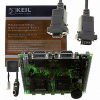
Description
KIT DEMOBOARD 8051 MCU W/CAN
Manufacturer
Atmel
Datasheet
1.AT89STK-06.pdf
(22 pages)
Specifications of AT89STK-06
Main Purpose
Interface, CAN
Embedded
*
Utilized Ic / Part
T89C51CC01/CC02, AT89C51CC03
Primary Attributes
*
Secondary Attributes
*
Lead Free Status / RoHS Status
Contains lead / RoHS non-compliant


3.1
3.1.1
3.1.1.1
3.1.1.2
3.1.2
3.1.2.1
AT89STK-06 Demo Board Software Demonstration Guide
In-System
Programming
Manual ISP Mode
Board Configuration
Operating Mode
Auto ISP Mode
Board Configuration
The on-chip memories and configuration bytes of the AT89C51CC0x parts can be pro-
grammed using the ISP mode of the device.
To use ISP mode, the board should be configured as follow:
To enter in ISP mode, press both the RESET (SW5) and ISP (SW4) buttons simulta-
neously. First release the RESET button and then the ISP button. The device enters in
ISP mode.
The Auto ISP is available only for parts with UART bootloader (-UA devices). It allows
the host PC application (Atmel FLIP software for example) to control the hardware con-
ditions from the serial lines RTS and DTR.
Thus with the Auto ISP mode, the user does not need to push the ISP and RESET
buttons.
To use Auto ISP mode, put the board in the same configuration as ISP mode and also:
POWER switch (SW1) on “ON” position
EA jumper should be open (internal code execution only).
Before using ISP mode for T89C51CC02 or T89C5115 device, be sure to close SP1
solder pad ( See Section "T89C51CC02/T89C5115 Support (SP1)", page 8).
Close RTS (JP4) jumper
Close DTR (JP5) jumper
Device Programming
Section 3
Rev. 4339C–CAN–07/05
3-11
Related parts for AT89STK-06
Image
Part Number
Description
Manufacturer
Datasheet
Request
R

Part Number:
Description:
KIT EVAL APPL MASS STORAGE
Manufacturer:
Atmel
Datasheet:

Part Number:
Description:
KIT STARTER FOR AT89C5131
Manufacturer:
Atmel
Datasheet:

Part Number:
Description:
KIT STARTER FOR AT83C24
Manufacturer:
Atmel
Datasheet:

Part Number:
Description:
EVAL BOARD FOR AT83C26
Manufacturer:
Atmel
Datasheet:

Part Number:
Description:
KIT STARTER FOR MCU AT8XC5122/23
Manufacturer:
Atmel
Datasheet:

Part Number:
Description:
KIT STARTER FOR AT89C51RX2
Manufacturer:
Atmel
Datasheet:


Part Number:
Description:
8-Bit Microcontroller with 4K Bytes Flash
Manufacturer:
ATMEL Corporation
Datasheet:

Part Number:
Description:
DEV KIT FOR AVR/AVR32
Manufacturer:
Atmel
Datasheet:
Part Number:
Description:
INTERVAL AND WIPE/WASH WIPER CONTROL IC WITH DELAY
Manufacturer:
ATMEL Corporation
Datasheet:
Part Number:
Description:
Low-Voltage Voice-Switched IC for Hands-Free Operation
Manufacturer:
ATMEL Corporation
Datasheet:
Part Number:
Description:
MONOLITHIC INTEGRATED FEATUREPHONE CIRCUIT
Manufacturer:
ATMEL Corporation
Datasheet:
Part Number:
Description:
AM-FM Receiver IC U4255BM-M
Manufacturer:
ATMEL Corporation
Datasheet:
Part Number:
Description:
Monolithic Integrated Feature Phone Circuit
Manufacturer:
ATMEL Corporation
Datasheet: