AT89STK-06 Atmel, AT89STK-06 Datasheet - Page 9
AT89STK-06
Manufacturer Part Number
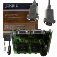
AT89STK-06
Description
KIT DEMOBOARD 8051 MCU W/CAN
Manufacturer
Atmel
Datasheet
1.AT89STK-06.pdf
(22 pages)
Specifications of AT89STK-06
Main Purpose
Interface, CAN
Embedded
*
Utilized Ic / Part
T89C51CC01/CC02, AT89C51CC03
Primary Attributes
*
Secondary Attributes
*
Lead Free Status / RoHS Status
Contains lead / RoHS non-compliant


2.5
2.5.1
Table 2-1. Default Jumper Setting
AT89STK-06 Demo Board Software Demo Guide
JP1
JP2
JP3
JP4
JP5
JP6
Reference
Board Settings
Jumpers
EA
MUTE
CANRes
RTS
DTR
Batt
PCB Name
The AT89STK-06 board has two types of settings:
Table 2-1, Table 2-2 and Table 2-3 provide an overview of the available settings and
test points.
Figure 2-10. Jumper Setting Definition
ON : allows external execution
OFF: Internal code execution
ON : Enable C51 generic extension board (optionnal) buzzer
OFF: Disable C51 generic extension board (optionnal) buzzer
ON : Enable CAN terminator resistor
OFF: Disable CAN terminator resistor
ON : Enable RTS line to control ISP mode (for AutoISP mode)
OFF: Disable RTS line to control ISP mode
ON : Enable DTR line to drive MCU reset (for AutoISP mode)
OFF: Disable DTR line to drive MCU reset
ON : Enable Battery charge
OFF: Disable Battery charge
Jumpers
Solder strap
Test points
jumper header
strap
Comments (guidelines)
Ex: 1-2
ON or
Hardware Description
Open (OFF)
Open (OFF)
Open (OFF)
Open (OFF)
Open (OFF)
Open (OFF)
4339C–CAN–07/05
OFF
Default
2-7
Related parts for AT89STK-06
Image
Part Number
Description
Manufacturer
Datasheet
Request
R

Part Number:
Description:
KIT EVAL APPL MASS STORAGE
Manufacturer:
Atmel
Datasheet:

Part Number:
Description:
KIT STARTER FOR AT89C5131
Manufacturer:
Atmel
Datasheet:

Part Number:
Description:
KIT STARTER FOR AT83C24
Manufacturer:
Atmel
Datasheet:

Part Number:
Description:
EVAL BOARD FOR AT83C26
Manufacturer:
Atmel
Datasheet:

Part Number:
Description:
KIT STARTER FOR MCU AT8XC5122/23
Manufacturer:
Atmel
Datasheet:

Part Number:
Description:
KIT STARTER FOR AT89C51RX2
Manufacturer:
Atmel
Datasheet:


Part Number:
Description:
8-Bit Microcontroller with 4K Bytes Flash
Manufacturer:
ATMEL Corporation
Datasheet:

Part Number:
Description:
DEV KIT FOR AVR/AVR32
Manufacturer:
Atmel
Datasheet:
Part Number:
Description:
INTERVAL AND WIPE/WASH WIPER CONTROL IC WITH DELAY
Manufacturer:
ATMEL Corporation
Datasheet:
Part Number:
Description:
Low-Voltage Voice-Switched IC for Hands-Free Operation
Manufacturer:
ATMEL Corporation
Datasheet:
Part Number:
Description:
MONOLITHIC INTEGRATED FEATUREPHONE CIRCUIT
Manufacturer:
ATMEL Corporation
Datasheet:
Part Number:
Description:
AM-FM Receiver IC U4255BM-M
Manufacturer:
ATMEL Corporation
Datasheet:
Part Number:
Description:
Monolithic Integrated Feature Phone Circuit
Manufacturer:
ATMEL Corporation
Datasheet: