EVL6563S-400W STMicroelectronics, EVL6563S-400W Datasheet - Page 19
EVL6563S-400W
Manufacturer Part Number
EVL6563S-400W
Description
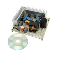
EVAL BOARD FOR L6563(400W)
Manufacturer
STMicroelectronics
Type
Motor / Motion Controllers & Driversr
Specifications of EVL6563S-400W
Main Purpose
Power Management, Power Factor Correction
Embedded
No
Utilized Ic / Part
L6563
Primary Attributes
400W Power Factor Correction and Preregulator Combination
Secondary Attributes
Transition Mode & Active Tracking Boost Function.
Maximum Operating Temperature
+ 60 C
Product
Power Management Development Tools
Lead Free Status / RoHS Status
Lead free / RoHS Compliant
For Use With/related Products
L6563S
Other names
497-10488
Available stocks
Company
Part Number
Manufacturer
Quantity
Price


AN2994
2.5
Brownout function
A dangerous event for any PFC is the operation during a mains undervoltage. This condition
may cause overheating of the power section due to an excess of RMS current. To protect
the PFC from this abnormal operation, a brownout protection is needed. It is basically a non-
latched shutdown function that has to be activated when a mains undervoltage condition is
detected.
The L6563S has a dedicated inhibit pin (RUN, #10) that embeds a comparator with
hysteresis and which stops the L6563S operation if the voltage applied is below its
threshold. Because the L6563S V
mains, the complete brownout function can be easily realized using a simple resistor divider
connected between the V
setting the turn-on threshold are R26 and R27 on the schematic in
shows a start-up tentative below the threshold. As visible at start-up, the RUN pin does not
allow the PFC start-up.
Figure 30
protection. In both cases, the mains voltages were increased or decreased slowly. As you
can see, at both turn-on and turn-off, there are no bouncing or starting attempts by the
converter.
Figure 29. EVL6563S-400W start-up attempt at 80 Vac, 60 Hz, full load
CH1: Output voltage
CH2: Pin #14 - Vcc voltage
CH3: Pin #10 - RUN
CH4: Pin #13 - Gate drive
and
Figure 31
show the waveforms of the circuit during operation of the brownout
FF
and RUN pins. In this demonstration board, the divider resistors
Doc ID 15796 Rev 2
FF
pin delivers a voltage signal proportional to the input
Test results and significant waveforms
Figure
1.
Figure 29
19/38
Related parts for EVL6563S-400W
Image
Part Number
Description
Manufacturer
Datasheet
Request
R

Part Number:
Description:
EVAL BOARD FOR L6563(100W)
Manufacturer:
STMicroelectronics
Datasheet:

Part Number:
Description:
EVAL BOARD FOR L6563(250W)
Manufacturer:
STMicroelectronics
Datasheet:

Part Number:
Description:
Power Management Modules & Development Tools Tranisition Mode PFC L6563S EVL Board
Manufacturer:
STMicroelectronics
Datasheet:

Part Number:
Description:
EVAL BOARD L6563 (200W)
Manufacturer:
STMicroelectronics
Datasheet:
Part Number:
Description:
STMicroelectronics [RIPPLE-CARRY BINARY COUNTER/DIVIDERS]
Manufacturer:
STMicroelectronics
Datasheet:
Part Number:
Description:
STMicroelectronics [LIQUID-CRYSTAL DISPLAY DRIVERS]
Manufacturer:
STMicroelectronics
Datasheet:

Part Number:
Description:
BOARD EVAL FOR MEMS SENSORS
Manufacturer:
STMicroelectronics
Datasheet:
Part Number:
Description:
NPN TRANSISTOR POWER MODULE
Manufacturer:
STMicroelectronics
Datasheet:
Part Number:
Description:
TURBOSWITCH ULTRA-FAST HIGH VOLTAGE DIODE
Manufacturer:
STMicroelectronics
Datasheet:
Part Number:
Description:
Manufacturer:
STMicroelectronics
Datasheet:
Part Number:
Description:
DIODE / SCR MODULE
Manufacturer:
STMicroelectronics
Datasheet:
Part Number:
Description:
DIODE / SCR MODULE
Manufacturer:
STMicroelectronics
Datasheet: