EVL6563S-400W STMicroelectronics, EVL6563S-400W Datasheet - Page 22
EVL6563S-400W
Manufacturer Part Number
EVL6563S-400W
Description
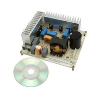
EVAL BOARD FOR L6563(400W)
Manufacturer
STMicroelectronics
Type
Motor / Motion Controllers & Driversr
Specifications of EVL6563S-400W
Main Purpose
Power Management, Power Factor Correction
Embedded
No
Utilized Ic / Part
L6563
Primary Attributes
400W Power Factor Correction and Preregulator Combination
Secondary Attributes
Transition Mode & Active Tracking Boost Function.
Maximum Operating Temperature
+ 60 C
Product
Power Management Development Tools
Lead Free Status / RoHS Status
Lead free / RoHS Compliant
For Use With/related Products
L6563S
Other names
497-10488
Available stocks
Company
Part Number
Manufacturer
Quantity
Price


Test results and significant waveforms
2.7
22/38
Overvoltage and open-loop protection
Normally, the voltage-control loop keeps the output voltage Vo of the PFC pre-regulator
close to its nominal value, set by the ratio of the resistors of the output divider (R9, R10, R11
and R12 in parallel to R13). The device’s PFC_OK pin (#7) is dedicated to monitoring the
output voltage with a separate resistor divider (R6, R7, R8 and R24). This divider has been
selected so that the voltage at the pin reaches 2.5 V if the output voltage exceeds a preset
value, usually higher than the maximum Vo that can be expected, also including worst-case
load/line transients.
When this function is triggered, the activity of the gate drive is immediately stopped until the
voltage on the PFC_OK pin drops below 2.4 V. Notice that R1, R2, R3 and R4 can be
selected without any constraints.
The unique criterion is that both dividers have to sink a current from the output bus, which
needs to be significantly higher than the current biasing the error amplifier and PFC_OK
comparator.
The OVP function described above can handle “normal” overvoltage conditions, that is,
those resulting from an abrupt load/line change or occurring at start-up. If the overvoltage is
generated by a feedback disconnection, for instance, when the upper resistor of the output
divider fails to open, an additional circuitry detects the voltage drop of the INV pin. If the
voltage on pin INV is lower than 1.66 V and at the same time the OVP is active, the feedback
failure is assumed. Hence, the gate drive activity is immediately stopped, the device is shut
down, its quiescent consumption is reduced to below 180 μA and the condition is latched as
long as the supply voltage of the IC stays above the UVLO threshold. At the same time, the
PWM_LATCH pin is asserted high. PWM_LATCH is an open-source output that can deliver
2.8 V minimum with a 0.25 mA load, intended for tripping a latched shutdown function of the
PWM controller IC in the cascaded DC-DC converter, so that the entire unit is latched off. In
this case, to resume operation, it is necessary to recycle the input power so that the Vcc
voltage of the L6563S goes below 6 V and that one of the PWM controller goes below its
UVLO threshold.
The PFC_OK pin doubles its function as a non-latched IC disable: a voltage below 0.23 V
will shut down the IC, reducing its consumption to below 2 mA. In this case, both
PWM_STOP and PWM_LATCH keep their high impedance status. To restart the IC, simply
let the voltage at the pin go above 0.27 V.
Note that this function offers a complete protection against not only feedback loop failures or
erroneous settings, but also against a failure of the protection itself. Either resistor of the
PFC_OK divider failing short or open or a PFC_OK pin floating will result in the IC being
shut down and the pre-regulator stopped.
The event of an open loop is captured in
intervention stopping the operation of the L6563S and the activation of the PWM_LATCH
pin.
Doc ID 15796 Rev 2
Figure
34, where you can see the protection
AN2994
Related parts for EVL6563S-400W
Image
Part Number
Description
Manufacturer
Datasheet
Request
R

Part Number:
Description:
EVAL BOARD FOR L6563(100W)
Manufacturer:
STMicroelectronics
Datasheet:

Part Number:
Description:
EVAL BOARD FOR L6563(250W)
Manufacturer:
STMicroelectronics
Datasheet:

Part Number:
Description:
Power Management Modules & Development Tools Tranisition Mode PFC L6563S EVL Board
Manufacturer:
STMicroelectronics
Datasheet:

Part Number:
Description:
EVAL BOARD L6563 (200W)
Manufacturer:
STMicroelectronics
Datasheet:
Part Number:
Description:
STMicroelectronics [RIPPLE-CARRY BINARY COUNTER/DIVIDERS]
Manufacturer:
STMicroelectronics
Datasheet:
Part Number:
Description:
STMicroelectronics [LIQUID-CRYSTAL DISPLAY DRIVERS]
Manufacturer:
STMicroelectronics
Datasheet:

Part Number:
Description:
BOARD EVAL FOR MEMS SENSORS
Manufacturer:
STMicroelectronics
Datasheet:
Part Number:
Description:
NPN TRANSISTOR POWER MODULE
Manufacturer:
STMicroelectronics
Datasheet:
Part Number:
Description:
TURBOSWITCH ULTRA-FAST HIGH VOLTAGE DIODE
Manufacturer:
STMicroelectronics
Datasheet:
Part Number:
Description:
Manufacturer:
STMicroelectronics
Datasheet:
Part Number:
Description:
DIODE / SCR MODULE
Manufacturer:
STMicroelectronics
Datasheet:
Part Number:
Description:
DIODE / SCR MODULE
Manufacturer:
STMicroelectronics
Datasheet: