EVL6563S-400W STMicroelectronics, EVL6563S-400W Datasheet - Page 5
EVL6563S-400W
Manufacturer Part Number
EVL6563S-400W
Description
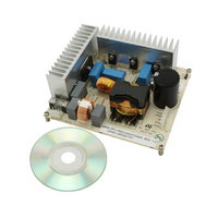
EVAL BOARD FOR L6563(400W)
Manufacturer
STMicroelectronics
Type
Motor / Motion Controllers & Driversr
Specifications of EVL6563S-400W
Main Purpose
Power Management, Power Factor Correction
Embedded
No
Utilized Ic / Part
L6563
Primary Attributes
400W Power Factor Correction and Preregulator Combination
Secondary Attributes
Transition Mode & Active Tracking Boost Function.
Maximum Operating Temperature
+ 60 C
Product
Power Management Development Tools
Lead Free Status / RoHS Status
Lead free / RoHS Compliant
For Use With/related Products
L6563S
Other names
497-10488
Available stocks
Company
Part Number
Manufacturer
Quantity
Price


AN2994
1
Main characteristics and circuit description
The EVL6563S-400W demonstration board has the following characteristics.
●
●
●
●
●
●
●
●
●
●
●
●
The demonstration board implements a power factor correction (PFC) pre-regulator
delivering 400 W of continuous power on a regulated 400 V rail from a wide-range mains
voltage, and providing for the reduction of the mains harmonics, thus complying with the
European norm EN61000-3-2 and the Japanese norm JEITA-MITI. This rail will be the input
for the cascaded isolated DC-DC converter that will provide the output voltages required by
the load.
The board is equipped with enough heat sinking to allow full-load operation in still air. With
an appropriate airflow and without any change in the circuit, the demonstration board can
easily deliver up to 450 W.
The controller is the L6563S (U1), integrating all the functions needed to control the PFC
stage and to interface with the downstream converter. The L6563S controller chip is
designed for transition-mode (TM) operation, where the boost inductor works next to the
boundary between continuous (CCM) and discontinuous conduction mode (DCM). However,
with a slightly different usage, the chip can operate so that the boost inductor works in CCM,
hence surpassing the limitations of TM operation in terms of power handling capability. The
gate-drive capability of the L6563S is also adequate to drive the MOSFETs used at higher
power levels. This approach, which couples the simplicity and cost-effectiveness of TM
operation with the high-current capability of CCM operation, is the fixed off time (FOT)
control. The control modulates the ON time of the power switch, while its OFF time is kept
constant. More precisely, the line-modulated FOT (LM FOT) is used, where the OFF time of
the power switch is not rigorously constant but is modulated by the instantaneous mains
voltage. Refer to [2] for a detailed description of this technique.
The power stage of the PFC is a conventional boost converter, connected to the output of
the rectifier bridge D2. It includes the coil L4, the diode D3 and the capacitors C6 and C7.
The boost switch is represented by the power MOSFETs Q1 and Q2. The NTC R2 limits the
inrush current at switch on. It has been connected to the DC rail, in series to the output
electrolytic capacitor, in order to improve the efficiency during low line operation.
Additionally, the splitting into two of the output capacitors (C6 and C7) means that the AC
current is mainly managed by the film capacitor C7, making the electrolytic cheaper
because it only has to bear the DC part.
Line voltage range: 90 to 265 Vac
Minimum line frequency (f
Regulated output voltage: 400 V
Rated output power: 400 W
Maximum 2f
Hold-up time: 22 ms (V
Maximum switching frequency: 85 kHz (Vin = 90 Vac, Pout = 400 W)
Minimum estimated efficiency: 90% (Vin = 90 Vac, Pout = 400 W)
Maximum ambient temperature: 50 °C
EMI: in accordance with EN55022 Class-B
PCB type and size: single side, 70 µm, CEM-1, 148.5 x 132 mm
Low profile design: 35 mm component maximum height
L
output voltage ripple: 10 V pk-pk
DROP
Doc ID 15796 Rev 2
L
): 47 Hz
after hold-up time: 300 V)
Main characteristics and circuit description
5/38
Related parts for EVL6563S-400W
Image
Part Number
Description
Manufacturer
Datasheet
Request
R

Part Number:
Description:
EVAL BOARD FOR L6563(100W)
Manufacturer:
STMicroelectronics
Datasheet:

Part Number:
Description:
EVAL BOARD FOR L6563(250W)
Manufacturer:
STMicroelectronics
Datasheet:

Part Number:
Description:
Power Management Modules & Development Tools Tranisition Mode PFC L6563S EVL Board
Manufacturer:
STMicroelectronics
Datasheet:

Part Number:
Description:
EVAL BOARD L6563 (200W)
Manufacturer:
STMicroelectronics
Datasheet:
Part Number:
Description:
STMicroelectronics [RIPPLE-CARRY BINARY COUNTER/DIVIDERS]
Manufacturer:
STMicroelectronics
Datasheet:
Part Number:
Description:
STMicroelectronics [LIQUID-CRYSTAL DISPLAY DRIVERS]
Manufacturer:
STMicroelectronics
Datasheet:

Part Number:
Description:
BOARD EVAL FOR MEMS SENSORS
Manufacturer:
STMicroelectronics
Datasheet:
Part Number:
Description:
NPN TRANSISTOR POWER MODULE
Manufacturer:
STMicroelectronics
Datasheet:
Part Number:
Description:
TURBOSWITCH ULTRA-FAST HIGH VOLTAGE DIODE
Manufacturer:
STMicroelectronics
Datasheet:
Part Number:
Description:
Manufacturer:
STMicroelectronics
Datasheet:
Part Number:
Description:
DIODE / SCR MODULE
Manufacturer:
STMicroelectronics
Datasheet:
Part Number:
Description:
DIODE / SCR MODULE
Manufacturer:
STMicroelectronics
Datasheet: