DTMFDECODER-RD Silicon Laboratories Inc, DTMFDECODER-RD Datasheet - Page 159
DTMFDECODER-RD
Manufacturer Part Number
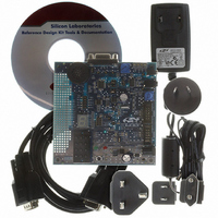
DTMFDECODER-RD
Description
KIT REF DESIGN DTMF DECODER
Manufacturer
Silicon Laboratories Inc
Specifications of DTMFDECODER-RD
Mfg Application Notes
DTMF Decoder Ref Design AppNote
Main Purpose
Telecom, DTMF Decoder
Embedded
No
Utilized Ic / Part
C8051F300
Primary Attributes
8kHz Sampling Rate ADC
Secondary Attributes
16 Goertzel Filters
Processor To Be Evaluated
C8051F300
Interface Type
RS-232
Lead Free Status / RoHS Status
Contains lead / RoHS non-compliant
Lead Free Status / RoHS Status
Lead free / RoHS Compliant, Contains lead / RoHS non-compliant
Other names
336-1283


16.2.2. Software Timer (Compare) Mode
In Software Timer mode, the PCA counter/timer value is compared to the module's 16-bit capture/compare
register (PCA0CPHn and PCA0CPLn). When a match occurs, the Capture/Compare Flag (CCFn) in
PCA0CN is set to logic 1 and an interrupt request is generated if CCF interrupts are enabled. The CCFn bit
is not automatically cleared by hardware when the CPU vectors to the interrupt service routine, and must
be cleared by software. Setting the ECOMn and MATn bits in the PCA0CPMn register enables Software
Timer mode.
Important Note About Capture/Compare Registers: When writing a 16-bit value to the PCA0 Capture/
Compare registers, the low byte should always be written first. Writing to PCA0CPLn clears the ECOMn bit
to ‘0’; writing to PCA0CPHn sets ECOMn to ‘1’.
PCA0CPLn
Write to
Reset
PCA0CPHn
Write to
0
1
ENB
ENB
Figure 16.5. PCA Software Timer Mode Diagram
W
M
P
1
6
n
x
C
O
M
E
n
PCA0CPMn
C
A
P
P
n
0 0
C
A
P
N
n
M
A
T
n
O
G
T
n
0 0
W
M
P
n
E
C
C
F
n
x
Enable
PCA
Timebase
Rev. 2.9
PCA0CPLn
PCA0L
16-bit Comparator
PCA0CPHn
C8051F300/1/2/3/4/5
PCA0H
Match
C
F
C
R
PCA0CN
0
1
C
C
F
2
C
C
F
1
C
C
F
0
PCA Interrupt
159
Related parts for DTMFDECODER-RD
Image
Part Number
Description
Manufacturer
Datasheet
Request
R

Part Number:
Description:
SMD/C°/SINGLE-ENDED OUTPUT SILICON OSCILLATOR
Manufacturer:
Silicon Laboratories Inc
Part Number:
Description:
Manufacturer:
Silicon Laboratories Inc
Datasheet:
Part Number:
Description:
N/A N/A/SI4010 AES KEYFOB DEMO WITH LCD RX
Manufacturer:
Silicon Laboratories Inc
Datasheet:
Part Number:
Description:
N/A N/A/SI4010 SIMPLIFIED KEY FOB DEMO WITH LED RX
Manufacturer:
Silicon Laboratories Inc
Datasheet:
Part Number:
Description:
N/A/-40 TO 85 OC/EZLINK MODULE; F930/4432 HIGH BAND (REV E/B1)
Manufacturer:
Silicon Laboratories Inc
Part Number:
Description:
EZLink Module; F930/4432 Low Band (rev e/B1)
Manufacturer:
Silicon Laboratories Inc
Part Number:
Description:
I°/4460 10 DBM RADIO TEST CARD 434 MHZ
Manufacturer:
Silicon Laboratories Inc
Part Number:
Description:
I°/4461 14 DBM RADIO TEST CARD 868 MHZ
Manufacturer:
Silicon Laboratories Inc
Part Number:
Description:
I°/4463 20 DBM RFSWITCH RADIO TEST CARD 460 MHZ
Manufacturer:
Silicon Laboratories Inc
Part Number:
Description:
I°/4463 20 DBM RADIO TEST CARD 868 MHZ
Manufacturer:
Silicon Laboratories Inc
Part Number:
Description:
I°/4463 27 DBM RADIO TEST CARD 868 MHZ
Manufacturer:
Silicon Laboratories Inc
Part Number:
Description:
I°/4463 SKYWORKS 30 DBM RADIO TEST CARD 915 MHZ
Manufacturer:
Silicon Laboratories Inc
Part Number:
Description:
N/A N/A/-40 TO 85 OC/4463 RFMD 30 DBM RADIO TEST CARD 915 MHZ
Manufacturer:
Silicon Laboratories Inc
Part Number:
Description:
I°/4463 20 DBM RADIO TEST CARD 169 MHZ
Manufacturer:
Silicon Laboratories Inc