DEMOBOARD TLE8201R Infineon Technologies, DEMOBOARD TLE8201R Datasheet - Page 38
DEMOBOARD TLE8201R
Manufacturer Part Number
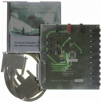
DEMOBOARD TLE8201R
Description
BOARD DEMO TLE8201R V1.0
Manufacturer
Infineon Technologies
Datasheet
1.TLE8201R.pdf
(45 pages)
Specifications of DEMOBOARD TLE8201R
Main Purpose
Power Management, High & Low Side Driver (Internal FET)
Embedded
No
Utilized Ic / Part
TLE8201
Primary Attributes
1 H-Bridge @ 3A, 4 Half Bridges- 2 @ 1A, 2 @ 0.5A, 5 High Side 1@ 2.5A, 4 @ 0..5A
Secondary Attributes
SPI Interface, Intended for Automotive Door
Lead Free Status / RoHS Status
Lead free / RoHS Compliant
Other names
DEMOBOARDTLE8201RIN


4.6.2
Electrical Characteristics OUT 8 - 11 (Lamp drivers)
8 V <
-40 C <
Pos. Parameter
Static Drain-source ON-Resistance
4.6.1
Switching Times
4.6.2
4.6.3
4.6.4
4.6.5
Short Circuit Protection
4.6.6
4.6.7
4.6.8
4.6.9
4.6.10 Shutdown delay time
Open Load Detection
4.6.11 Pull-up current
4.6.12 Detection Threshold
4.6.13 Delay time
Leakage Current
4.6.14 OFF-state output current
1)
Data Sheet Rev. 2.0
Not subject to production test - specified by design.
V
Turn-ON delay time
Output rise-time
Turn-OFF delay time
Output fall-time
Over-current shutdown
threshold
Over-current shutdown
threshold voltage
Short circuit current
Shutdown delay time
High-side switch
S
T
< 20 V; 4.75 V <
j
Electrical Characteristics
< 150 C; unless otherwise specified
1)
V
CC
< 5.25 V; INH = High; all outputs open;
Sym-
bol
R
t
t
t
t
I
V
I
t
t
I
V
t
I
dONH8
rise8
dOFFH8
fall8
dSDon8
dSD8
dOC8
SD8
SC8
OpL8
QL
DSON8
SD8
OpL8
38
min. typ.
–
–
–
5
–
7
1.8
1.5
-
125
10
100
2
–
–
Limit Values
–
–
5
10
25
15
2.9
2,5
4.2
200
25
–
–
–
–
max.
0.5
0.8
15
30
50
30
3.5
3.3
-
350
60
250
4
200
5
Unit Conditions
A
V
A
µs
µs
V
s
s
s
s
A
s
A
I
T
I
V
resistive load of
25
Figure 19
at switching-on
in on-state
V
–
–
V
OUT
OUT
j
S
OUT
OUT
TLE 8201R
= 25 C
= 14 V,
, see
= +0.5 A;
= +0.5 A
2006-06-07
= 4V
= GND
Related parts for DEMOBOARD TLE8201R
Image
Part Number
Description
Manufacturer
Datasheet
Request
R

Part Number:
Description:
BOARD DEMO FOR TLE6208-3G
Manufacturer:
Infineon Technologies
Datasheet:

Part Number:
Description:
BOARD DEMO FOR TLE6208-6G
Manufacturer:
Infineon Technologies
Datasheet:

Part Number:
Description:
BOARD DEMO FOR TLE 6288R
Manufacturer:
Infineon Technologies
Datasheet:

Part Number:
Description:
BOARD DEMO FOR TLE 6214L
Manufacturer:
Infineon Technologies
Datasheet:

Part Number:
Description:
BOARD DEMO FOR TLE 7209-2R
Manufacturer:
Infineon Technologies
Datasheet:

Part Number:
Description:
BOARD DEMO PROFET V2.0BTS
Manufacturer:
Infineon Technologies
Datasheet:

Part Number:
Description:
BOARD DEMO FOR TLE 6244X
Manufacturer:
Infineon Technologies
Datasheet:

Part Number:
Description:
BOARD DEMO FOR TLE 6365 REV.4
Manufacturer:
Infineon Technologies
Datasheet:

Part Number:
Description:
BOARD DEMO FOR TLE 6389-2GV
Manufacturer:
Infineon Technologies
Datasheet:

Part Number:
Description:
BOARD DEMO FOR TLE 6389-2 GV50
Manufacturer:
Infineon Technologies
Datasheet:

Part Number:
Description:
Manufacturer:
Infineon Technologies AG
Datasheet:
Part Number:
Description:
Manufacturer:
Infineon Technologies AG
Datasheet:
Part Number:
Description:
Manufacturer:
Infineon Technologies AG
Datasheet:
Part Number:
Description:
Manufacturer:
Infineon Technologies AG
Datasheet:
Part Number:
Description:
Manufacturer:
Infineon Technologies AG
Datasheet: