DEMOBOARD TLE8201R Infineon Technologies, DEMOBOARD TLE8201R Datasheet - Page 5
DEMOBOARD TLE8201R
Manufacturer Part Number
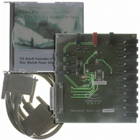
DEMOBOARD TLE8201R
Description
BOARD DEMO TLE8201R V1.0
Manufacturer
Infineon Technologies
Datasheet
1.TLE8201R.pdf
(45 pages)
Specifications of DEMOBOARD TLE8201R
Main Purpose
Power Management, High & Low Side Driver (Internal FET)
Embedded
No
Utilized Ic / Part
TLE8201
Primary Attributes
1 H-Bridge @ 3A, 4 Half Bridges- 2 @ 1A, 2 @ 0.5A, 5 High Side 1@ 2.5A, 4 @ 0..5A
Secondary Attributes
SPI Interface, Intended for Automotive Door
Lead Free Status / RoHS Status
Lead free / RoHS Compliant
Other names
DEMOBOARDTLE8201RIN


2.2
Pin
cooling
tab
1, 18,
19, 36
2
3
4, 15, 23,
26, 30, 33
5
6
7
8
9
10
11
12
Data Sheet Rev. 2.0
Pin Definitions and Functions
Symbol
GND
GND
OUT5
OUT6
Vs
INH
PWM1
PWM2
ISO
Vcc
DO
CLK
CSN
Function
Cooling tab, internally connected to GND; to reduce thermal
resistance place cooling areas and thermal vias on PCB.
Ground; internally connected to cooling tab (heat slug).
Power-Output of half-bridge 5; DMOS half-bridge
Power-Output of half-bridge 6; DMOS half-bridge.
Power supply; needs decoupling capacitors to GND. > 47µF
electrolytic in parallel with 100nF ceramic is recommended. All
Vs pins must be connected externally
Inhibit; active low. Sets the device in sleep mode with low
current consumption when left open or pulled to LOW. Has an
internal pull down current source
Logic Input for direct power stage control; direct input to
control the high-side switches selected by the SPI xsel1 bits in
control register CtrlReg01
Logic Input for direct power stage control; direct input to
control the switches selected by the SPI xsel2 bits in control
register CtrlReg11
Current sense output; Mirrors the current of the high-side
switch selected by the current sense multiplexer control bits ISx
Logic Supply Voltage; needs decoupling capacitors to GND
(pin 1). 10µF electrolytic in parallel with 10nF ceramic is
recommended
Serial Data Output; Transfers data to the master when the chip
is selected by CSN=LOW. Data transmission is synchronized by
CLK, DO state is changed on the rising edge of CLK. The most
significant bit (MSB) is transferred first. The pin is tristated as
long as CSN=HIGH
Serial Data Clock Input; Receives the clock signal from the
master and clocks the SPI shift register. Has an internal pull
down current source
Serial Port Chip Select Not Input; SPI communication is
enabled by pulling CSN to LOW. CLK must be LOW during the
transition of CSN. The CSN-pin has an internal pull-up current
source
5
Pin Configuration
TLE 8201R
2006-06-07
Related parts for DEMOBOARD TLE8201R
Image
Part Number
Description
Manufacturer
Datasheet
Request
R

Part Number:
Description:
BOARD DEMO FOR TLE6208-3G
Manufacturer:
Infineon Technologies
Datasheet:

Part Number:
Description:
BOARD DEMO FOR TLE6208-6G
Manufacturer:
Infineon Technologies
Datasheet:

Part Number:
Description:
BOARD DEMO FOR TLE 6288R
Manufacturer:
Infineon Technologies
Datasheet:

Part Number:
Description:
BOARD DEMO FOR TLE 6214L
Manufacturer:
Infineon Technologies
Datasheet:

Part Number:
Description:
BOARD DEMO FOR TLE 7209-2R
Manufacturer:
Infineon Technologies
Datasheet:

Part Number:
Description:
BOARD DEMO PROFET V2.0BTS
Manufacturer:
Infineon Technologies
Datasheet:

Part Number:
Description:
BOARD DEMO FOR TLE 6244X
Manufacturer:
Infineon Technologies
Datasheet:

Part Number:
Description:
BOARD DEMO FOR TLE 6365 REV.4
Manufacturer:
Infineon Technologies
Datasheet:

Part Number:
Description:
BOARD DEMO FOR TLE 6389-2GV
Manufacturer:
Infineon Technologies
Datasheet:

Part Number:
Description:
BOARD DEMO FOR TLE 6389-2 GV50
Manufacturer:
Infineon Technologies
Datasheet:

Part Number:
Description:
Manufacturer:
Infineon Technologies AG
Datasheet:
Part Number:
Description:
Manufacturer:
Infineon Technologies AG
Datasheet:
Part Number:
Description:
Manufacturer:
Infineon Technologies AG
Datasheet:
Part Number:
Description:
Manufacturer:
Infineon Technologies AG
Datasheet:
Part Number:
Description:
Manufacturer:
Infineon Technologies AG
Datasheet: