DEMOBOARD TLE8201R Infineon Technologies, DEMOBOARD TLE8201R Datasheet - Page 9
DEMOBOARD TLE8201R
Manufacturer Part Number
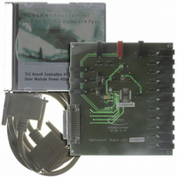
DEMOBOARD TLE8201R
Description
BOARD DEMO TLE8201R V1.0
Manufacturer
Infineon Technologies
Datasheet
1.TLE8201R.pdf
(45 pages)
Specifications of DEMOBOARD TLE8201R
Main Purpose
Power Management, High & Low Side Driver (Internal FET)
Embedded
No
Utilized Ic / Part
TLE8201
Primary Attributes
1 H-Bridge @ 3A, 4 Half Bridges- 2 @ 1A, 2 @ 0.5A, 5 High Side 1@ 2.5A, 4 @ 0..5A
Secondary Attributes
SPI Interface, Intended for Automotive Door
Lead Free Status / RoHS Status
Lead free / RoHS Compliant
Other names
DEMOBOARDTLE8201RIN


4
4.1
4.1.1
The TLE 8201R has two power supply inputs: All power drivers are connected to the
supply voltage
logic part is supplied by a separate Voltage
The advantage of this system is that information stored in the logic remains intact in the
event of short-term failures in the supply voltage
to operate after
A rising edge on
power-on. All data stored internally is deleted, and the outputs are switched to high-
impedance status (tristate).
4.1.2
The TLE 8201R can be put in a low current-consumtion mode by setting the input INH
to LOW. The INH pin has an internal pull-down current source. In sleep-mode, all output
transistors are turned off and the SPI is not operating. When enabling the IC by setting
INH from L to H, a Power-On Reset is performed as described above.
4.1.3
The TLE 8201R requires an external reverse polarity protection. The gate-driver
(charge-pump output) for an external n-channel logic-level MOS-FET is integrated. The
gate voltage is provided at pin GO which should be connected as shown in the
application diagram.
4.1.4
Electrical Characteristics
8 V <
-40 C <
Pos.
Current Consumption
4.1.1
4.1.2
Data Sheet Rev. 2.0
V
S
Parameter
Supply current
Logic supply current
T
< 20 V; 4.75 V <
j
Block Description and Electrical Characteristics
Power Supply
General
Sleep-Mode
Reverse Polarity
Electrical Characteristics
< 150 C; unless otherwise specified
V
V
S
S
V
which is connected to the automotive 12 V board-net. The internal
has recovered, without having to be reprogrammed.
CC
triggers an internal Power-On Reset (POR) to initialize the IC at
V
CC
< 5.25 V; INH = High; all outputs open;
Block Description and Electrical Characteristics
Sym-
bol
I
I
S
CC
9
V
CC
min. typ.
–
–
= 5 V.
Limit Values
V
S
. The system can therefore continue
3.0
5
max.
7.0
10
Unit Conditions
mA
mA
–
SPI not active
TLE 8201R
2006-06-07
Related parts for DEMOBOARD TLE8201R
Image
Part Number
Description
Manufacturer
Datasheet
Request
R

Part Number:
Description:
BOARD DEMO FOR TLE6208-3G
Manufacturer:
Infineon Technologies
Datasheet:

Part Number:
Description:
BOARD DEMO FOR TLE6208-6G
Manufacturer:
Infineon Technologies
Datasheet:

Part Number:
Description:
BOARD DEMO FOR TLE 6288R
Manufacturer:
Infineon Technologies
Datasheet:

Part Number:
Description:
BOARD DEMO FOR TLE 6214L
Manufacturer:
Infineon Technologies
Datasheet:

Part Number:
Description:
BOARD DEMO FOR TLE 7209-2R
Manufacturer:
Infineon Technologies
Datasheet:

Part Number:
Description:
BOARD DEMO PROFET V2.0BTS
Manufacturer:
Infineon Technologies
Datasheet:

Part Number:
Description:
BOARD DEMO FOR TLE 6244X
Manufacturer:
Infineon Technologies
Datasheet:

Part Number:
Description:
BOARD DEMO FOR TLE 6365 REV.4
Manufacturer:
Infineon Technologies
Datasheet:

Part Number:
Description:
BOARD DEMO FOR TLE 6389-2GV
Manufacturer:
Infineon Technologies
Datasheet:

Part Number:
Description:
BOARD DEMO FOR TLE 6389-2 GV50
Manufacturer:
Infineon Technologies
Datasheet:

Part Number:
Description:
Manufacturer:
Infineon Technologies AG
Datasheet:
Part Number:
Description:
Manufacturer:
Infineon Technologies AG
Datasheet:
Part Number:
Description:
Manufacturer:
Infineon Technologies AG
Datasheet:
Part Number:
Description:
Manufacturer:
Infineon Technologies AG
Datasheet:
Part Number:
Description:
Manufacturer:
Infineon Technologies AG
Datasheet: