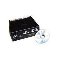
DM300022 Microchip Technology, DM300022 Datasheet - Page 14

DM300022
Manufacturer Part Number
DM300022
Description
MODULE PWR DSPICDEM MC1L LV 3PHS
Manufacturer
Microchip Technology
Specifications of DM300022
Main Purpose
Power Management, Motor Control
Embedded
Yes, MCU, 16-Bit
Utilized Ic / Part
dsPIC33FJxxxMC
Primary Attributes
3-Phase Low Voltage Power Module
Secondary Attributes
Motion Sensor Inputs: Hall Sensors or Optical Encoder
Silicon Manufacturer
Microchip
Silicon Core Number
DsPICDEM MC1L
Kit Application Type
Power Management - Motor Control
Application Sub Type
3 Phase Motor
Silicon Family Name
Piccolo
Rohs Compliant
Yes
Lead Free Status / RoHS Status
Lead free / RoHS Compliant
dsPICDEM™ MC1L 3-Phase Low Voltage Power Module
DS70097A-page 8
Using output connections 6 and 7, the user may connect an external braking resistor.
The user should consider the maximum and average power to be dissipated at the
required DC bus voltage when considering the resistor value. They should also
consider the peak allowable resistor current of 20A. For example, if regulating at 24V
then a 1.2Ω minimum value should be used which would allow 480W (at most) to be
dissipated.
The user may feed in a DC supply using output connections 5 and 7. Using these
terminals, the input current rating increases to 20A (RMS) continuous, but the inverter
output current rating is unaffected. Thus more output power may be used. Note that if
using the auxiliary DC input, the internal fuse, soft-start, reverse voltage and over-cur-
rent protection is bypassed. It is up to the user to ensure adequate external protection
circuitry is used and incoming DC voltage is regulated.
1.2.3
The system has been designed so that the Microchip dsPICDEM MC1 Motor Control
Development Board (02-01648) plugs directly into the 37-pin, D-Type connector.
Section 1.8 “User Signal Connector Pinout (37-Pin, D-Type)” contains details of
the pin allocation.
Correct operation with the use of an extension cable can not be guaranteed as it may
introduce additional noise. If an extension is used, it should be as short as possible
and shielded cable should be used.
The power module derives its low voltage power supplies from the control PCB. The
supplies on the isolated supply are taken directly from the control PCB via the 37-pin
connector. The supplies on the live side of the isolation barrier are derived using an
isolating DC-DC converter that is connected to the digital +5V supply input on the
37-pin connector. In this way, the power module may be used at any input voltage up
to the maximum. This arrangement is shown in Figure 1-4.
Connecting To The Control Board
© 2003 Microchip Technology Inc.


