DM300022 Microchip Technology, DM300022 Datasheet - Page 27

DM300022
Manufacturer Part Number
DM300022
Description
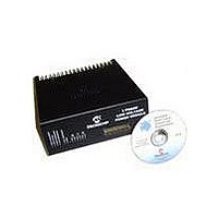
MODULE PWR DSPICDEM MC1L LV 3PHS
Manufacturer
Microchip Technology
Specifications of DM300022
Main Purpose
Power Management, Motor Control
Embedded
Yes, MCU, 16-Bit
Utilized Ic / Part
dsPIC33FJxxxMC
Primary Attributes
3-Phase Low Voltage Power Module
Secondary Attributes
Motion Sensor Inputs: Hall Sensors or Optical Encoder
Silicon Manufacturer
Microchip
Silicon Core Number
DsPICDEM MC1L
Kit Application Type
Power Management - Motor Control
Application Sub Type
3 Phase Motor
Silicon Family Name
Piccolo
Rohs Compliant
Yes
Lead Free Status / RoHS Status
Lead free / RoHS Compliant
© 2003 Microchip Technology Inc.
• R84, R85, R88 and R89 – The resistors form the differential configuration of the
• LK5 and LK6 – These allow two different gain settings to be used by shorting out
• LK4 – Provision is made for either bipolar or unipolar sensing by changing this
Other points to note:
• No common mode filtering has been used, as the amplifier's inherent common
• Note that the output of the op amp is not glitch-free during switching transitions,
• The self-inductance of the shunts (approx. 10nH) causes an additional voltage to
1.5.6.3
In addition to the three inverter leg shunts, provision has been made to monitor the
current in the -DC bus. In many applications, the information contained in this signal
alone is sufficient to provide the required closed loop control. The operating range and
the quality of control will dictate whether a bus shunt alone can be used. Clearly, it is
the cheapest of all schemes to implement.
The current that the shunt has flowing in it at any given time depends on the state of
all three inverter legs. It should be recalled that having both switches in the same leg
on at the same time is not allowed. The top switch being off (Top Fire = 0) assumes a
bottom switch is on. It does not matter whether the current actually flows in the switch
or the anti-parallel diode. The result depends only on the magnitude and direction of
the output currents.
TABLE 1-5:
From Table 1-5 it is clear that bipolar sensing requires with the same scaling as that
used for the inverter leg shunts. It can be seen that for the 000 and 111 conditions
(which corresponds to zero output phase voltage), no information is available. This
can cause considerable problems if operation at low output voltages is required when
using sinusoidal modulation.
amplifier.
R85 and R89. Note that both links must be used together for correct operation.
link. It changes the non-inverting input reference point between 2.5V and 0V.
Bipolar sensing is required for applications using sinusoidal modulation, whereas
unipolar sensing is sufficient for other applications.
mode rejection is sufficient and it requires tight tolerance components to be
effective.
but tracks the current rapidly. It is assumed that suitable synchronization of the
sampling of the output is used to reject the glitches.
be produced proportional to the rate of change of current. For typical motors, this
additional voltage is negligible, as the inductance is high enough to ensure a low
rate of change of current. If a low inductance load is used, the effect of the
additional voltage will have to be compensated for in the user's software.
Fire R Top
0
0
0
0
1
1
1
1
DC BUS SHUNT RESISTOR FEEDBACK
DC BUS SHUNT RESISTOR FEEDBACK
Phase Y Top
0
0
1
1
0
0
1
1
Phase B Top
0
1
0
1
0
1
0
1
Set Up and Operation
DC Bus Shunt
DS70097A-page 21
+IB
+IY
+IR
-IR
-IY
-IB
0
0


