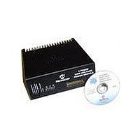
DM300022 Microchip Technology, DM300022 Datasheet - Page 31

DM300022
Manufacturer Part Number
DM300022
Description
MODULE PWR DSPICDEM MC1L LV 3PHS
Manufacturer
Microchip Technology
Specifications of DM300022
Main Purpose
Power Management, Motor Control
Embedded
Yes, MCU, 16-Bit
Utilized Ic / Part
dsPIC33FJxxxMC
Primary Attributes
3-Phase Low Voltage Power Module
Secondary Attributes
Motion Sensor Inputs: Hall Sensors or Optical Encoder
Silicon Manufacturer
Microchip
Silicon Core Number
DsPICDEM MC1L
Kit Application Type
Power Management - Motor Control
Application Sub Type
3 Phase Motor
Silicon Family Name
Piccolo
Rohs Compliant
Yes
Lead Free Status / RoHS Status
Lead free / RoHS Compliant
© 2003 Microchip Technology Inc.
1.5.8.3
The requirement for operation over a wide range of input voltages resulted in using
the +5V supply coming from the control board as the power source for all the low
voltage power supplies. This was true for both the isolated and live sides of the
system. The power supply circuitry on the live side is described below:
• U18 – An isolating 1W unregulated DC-DC converter with 5V input and 15V
• L4 and C83 – A filter to reduce the reflected ripple on the +5V supply from the
• L3 and C77 – A filter to reduce the magnitude of the ripple on the live +15V
• U5 – A 5V linear regulator for the live control circuit supplies.
• D4 – A 1A diode to protect U5 against reverse bias during power-down.
• R61 – A 0R resistor linking the low voltage power supply star point to the -DC bus.
1.5.9
1.5.9.1
Given the development nature of the system, robust independent FAULT protection is
provided on the power board rather than relying on software intervention. Five
different fault categories are used to indicate a FAULT to the user. Four of the fault
categories are detected on the live side. All FAULTs are latched and automatically
disable all firing commands. In a commercial application using the dsPIC device,
much of the hardware described below may be eliminated. In particular, the latches
are not required as the Output Compare and Motor Control PWM modules both have
dedicated fault inputs that can be configured to shutdown PWM outputs to their
inactive state.
The operation of the fault action is described below:
• D35-D38 and R114 – These form an active high wire OR of all four (live) FAULT
• R113, Q13, R110, D34, and Q14 – These components act to shutdown the brake
• U15 and R151 – If FAULT is asserted, current flows via R151 to cause the
• R176 and Q15 – If a Hall over-current is detected on the isolated side, the base
• D43, D44 and R172 – These form an active low wire OR of the isolated and live
(nominal) output. The +15V supply is used for the gate drive of the power devices
and the comparators on the live side of the isolation barrier.
control board caused by the DC-DC converter.
supply.
signals. R114 provides a passive pull-down during normal operation. The resulting
FAULT signal is used to directly shutdown the inverter gate drive ICs via their
shutdown logic input.
chopper during a FAULT. Q14 must be on for the detector stage of their
optocouplers to be powered. Under normal conditions, D34 and R110 provide the
base current for Q14. If the FAULT line is asserted, causing Q13 to turn on, or if
the +15V supply drops below approximately 10V, then Q14 turns off.
(open-collector) output of U15 to turn on. This indicates back to the isolated side
that a FAULT has occurred on the live side.
current for Q15 that normally flows via R176 is removed. As all the firing
command optocoupler emitters return via Q15, when Q15 is off, no firing can take
place.
fault indications for feedback to the dsPIC device.
LOW VOLTAGE POWER SUPPLIES (APPENDIX A SHEET 5 AND 8)
FAULT Protection (Appendix A Sheets 4, 5 and 6)
INTRODUCTION
Set Up and Operation
DS70097A-page 25


