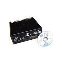
DM300022 Microchip Technology, DM300022 Datasheet - Page 29

DM300022
Manufacturer Part Number
DM300022
Description
MODULE PWR DSPICDEM MC1L LV 3PHS
Manufacturer
Microchip Technology
Specifications of DM300022
Main Purpose
Power Management, Motor Control
Embedded
Yes, MCU, 16-Bit
Utilized Ic / Part
dsPIC33FJxxxMC
Primary Attributes
3-Phase Low Voltage Power Module
Secondary Attributes
Motion Sensor Inputs: Hall Sensors or Optical Encoder
Silicon Manufacturer
Microchip
Silicon Core Number
DsPICDEM MC1L
Kit Application Type
Power Management - Motor Control
Application Sub Type
3 Phase Motor
Silicon Family Name
Piccolo
Rohs Compliant
Yes
Lead Free Status / RoHS Status
Lead free / RoHS Compliant
© 2003 Microchip Technology Inc.
• A serial communication interface – A simplified two-wire SPI (Clock and Data
• Pulse width modulation at constant frequency – This was rejected partly due to
• Frequency modulation – This was considered given pulse distortion by the
The actual hardware is described below:
• U34 – The PIC12C671. Note that the PIC microcontroller is reset whenever the
• R122 – The bottom resistor in the |VAC| pot down chain used on the high voltage
• C43 – The filtering capacitor for the |VAC| pot down chain, which is left in,
• R10, R13, R14, R140, R141 – These form a potential divider so that the maximum
• C57 – this acts to filter out any noise spikes on the DC bus voltage sensing.
• D40, D42 – clamping diodes to protect the PIC microcontroller inputs.
• U16, U17 – low current (1.6 mA), medium speed (1 MHz) optocouplers to provide
• R149, R150 – series resistors that help to set the current through the optocoupler
• C64, C70 – speed up capacitors to help reduce the effect of the optocoupler's
• R170, R171 – pull-up resistors for the open collector outputs of U16 and U17.
1.5.7.3
Knowledge of the actual inverter output voltage is useful for two different uses. The
first is for accurately compensating for output voltage errors due to dead time and
power device voltage drops. This can be especially important for high current low
voltage systems with high PWM frequencies and high performance requirements. The
second use is for back EMF sensing for sensorless position detection schemes for
Brushless Permanent Magnet (BPM) and other types of motors.
Out). It would operate as a master with the dsPIC device as the slave. Given the
PIC12C671 does not have a hardware SPI module, the interface would be
reproduced in software. The code latency was to be used for ADC acquisition and
conversion timing. This was the method chosen and the code is given in
Appendix B along with a diagram showing the transmission data cycle. Note that
the code is the same as that used for the high voltage version of the power
module and so transmits a second feedback signal that will read ‘0’.
concerns over distortion of the pulse width by economic optocouplers. Also, it was
thought that it would not be possible to provide the required bandwidth, while
maintaining the 8-bit resolution of the captured data, given the lack of a hardware
PWM module.
optocouplers ceased to be an issue. However, concerns about how the bandwidth
of the feedback could be maintained over the 8-bit data range led to its rejection.
RESET line is asserted, as this pin has been configured as the MCLR. This allows
correct synchronization of the SPI with the dsPIC device to be established. The
RESET line must be asserted for a minimum pulse width of 2 µs.
version of the power module. This is left in to ensure the ADC input is not floating.
although not required.
expected voltage on BUS_SENSE is 4.5V. Note that HALF_BUS_SENSE is used
by the sensorless position detection comparators (see Section 1.5.7.3 “Inverter
Output Voltage Feedback and Sensorless Detection”).
the isolation for the clock and data lines.
emitters. They are sized to allow a minimum of 1.8 mA to flow.
emitter capacitance at high data rates.
INVERTER OUTPUT VOLTAGE FEEDBACK AND SENSORLESS
DETECTION
Set Up and Operation
DS70097A-page 23


