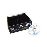
DM300022 Microchip Technology, DM300022 Datasheet - Page 17

DM300022
Manufacturer Part Number
DM300022
Description
MODULE PWR DSPICDEM MC1L LV 3PHS
Manufacturer
Microchip Technology
Specifications of DM300022
Main Purpose
Power Management, Motor Control
Embedded
Yes, MCU, 16-Bit
Utilized Ic / Part
dsPIC33FJxxxMC
Primary Attributes
3-Phase Low Voltage Power Module
Secondary Attributes
Motion Sensor Inputs: Hall Sensors or Optical Encoder
Silicon Manufacturer
Microchip
Silicon Core Number
DsPICDEM MC1L
Kit Application Type
Power Management - Motor Control
Application Sub Type
3 Phase Motor
Silicon Family Name
Piccolo
Rohs Compliant
Yes
Lead Free Status / RoHS Status
Lead free / RoHS Compliant
© 2003 Microchip Technology Inc.
Although not necessary for correct operation of the system, it is common practice to
eliminate very narrow firing commands. This is because they will have negligible effect
on the output waveform but incur additional switching loss. It is suggested that a duty
cycle that gives transistor on or off times of less than 100 ns be eliminated by rounding
the duty cycle up or down as appropriate. Note that pulses, which are narrower than
the dead time set in the Motor Control PWM module, are automatically eliminated.
In order to provide an economic design, so-called bootstrap power supplies are used
for the high side inverter switches (see Section Section 1.5.3.3 “Gate Drive” for
details). As the charging path for these is only made when the corresponding low side
switch or diode conducts, this places some minor restrictions on modulation. These
are as follows:
1. When the power module is first energized after a period of time where no
2. If the user is continuously modulating all the low side switches as part of their
3. In extreme circumstances, it is possible that the high side bootstrap supply will
1.2.6
1.2.6.1
The power module may be operated in two distinct ways with respect to signal
isolation. This effects which of the feedback signals are available. All feedback signals
are preconditioned and scaled within the power module. Which particular set of
feedback signals the user requires will change depending on the application. Typically
industrial applications tend to use isolated signals for both safety, noise and
performance reasons. More cost-sensitive applications, and especially those that
have little or no user input, tend to run the control electronics live and use non-isolated
feedback signals. High current applications may use isolated Hall effect current
transducers, due to issues of power dissipation in shunt resistors.
Note: The user should verify that all modulation frequencies and dead time
modulation has taken place, all low side switches should be turned on for 2-3 µs.
This ensures the bootstrap supplies are "primed". This can be done simply by
using the output override facility in the dsPIC Motor Control PWM module by
setting the correct bits in the OVDCON register. Care should be taken to ensure
a shoot-through does not accidentally occur. The possibility of a shoot-through
fault will be minimized if the dsPIC Motor Control PWM module is operated in the
complementary Output mode (module default).
PWM strategy, the "priming" step is not strictly necessary, as it will happen auto-
matically. There will however, be a delay of variable duration before the high side
switches actually fire. The delay will depend on the particular operating
circumstances and whether it is acceptable or not will depend on the particular
application.
discharge while the system is running. This will not happen for typical sinusoidal
modulation schemes provided an inductive load (e.g., a motor) is connected. If a
bootstrap supply collapses, an under-voltage lockout will automatically occur to
protect the high side switch entering the linear region of operation. The high side
switch is turned off whatever the command. The lockout is automatically cleared
when the bootstrap supply is restored and the next turn-on edge occurs. If
necessary, the user should periodically apply a refresh pulse to the low side
switch in a similar manner to that described for "priming".
Power Module Feedback Signals
INTRODUCTION
settings are correct using an oscilloscope before connecting the control
PCB to the power module.
Set Up and Operation
DS70097A-page 11


