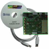
EVAL-AD7877EBZ Analog Devices Inc, EVAL-AD7877EBZ Datasheet - Page 16

EVAL-AD7877EBZ
Manufacturer Part Number
EVAL-AD7877EBZ
Description
BOARD EVALUATION FOR AD7877
Manufacturer
Analog Devices Inc
Datasheets
1.AD7877ACBZ-REEL7.pdf
(44 pages)
2.EVAL-AD7877EBZ.pdf
(16 pages)
3.EVAL-AD7877EBZ.pdf
(44 pages)
Specifications of EVAL-AD7877EBZ
Main Purpose
Interface, Touch Screen Controller
Embedded
No
Utilized Ic / Part
AD7877
Primary Attributes
4-Wire Resistive Touch Screen Controller, SPI Interface, On-Chip: Temp Sensor, Voltage Reference, 8-Bit DAC
Secondary Attributes
USB GUI, LCD Noise Reduction Feature, 2.7 ~ 5.25 V, Wake Up on Touch Feature
Lead Free Status / RoHS Status
Lead free / RoHS Compliant
AD7877
For greater accuracy, the ratiometric method has two significant
advantages:
•
•
The disadvantage of the ratiometric method is that the screen
must be powered up at all times because it provides the
reference voltage for the ADC.
TOUCH-PRESSURE MEASUREMENT
The pressure applied to the touch screen via a pen or finger can
also be measured with the AD7877 using some simple calcula-
tions. The contact resistance between the X and Y plates is
measured providing a good indication of the size of the
depressed area and, therefore, the applied pressure. The area of
the spot that is touched is proportional to the size of the object
touching it. The size of this resistance (R
using two different methods.
First Method
The first method requires the user to know the total resistance
of the X-plate tablet (R
required:
• Measurement of the X position, X
• Measurement of the Y− input with the excitation voltage
• Measurement of the X+ input with the excitation voltage
These three measurements are illustrated in Figure 31.
The AD7877 has two special ADC channel settings that
configure the X and Y switches for Z1 and Z2 measurement and
store the results in the Z1 and Z2 results registers. The Z1
measurement is ADC Channel 1010b, and the result is stored in
the register with Read Address 11010b. The Z2 measurement is
ADC Channel 0010b, and the result is stored in the register with
Read Address 10010b.
The touch resistance can then be calculated using the following
equation:
applied to Y+ and X− (Z1 measurement).
applied to Y+ and X− (Z2 measurement).
R
TOUCH
The reference to the ADC is provided from the actual
voltage across the screen; therefore, when the voltage drops
across the switches, it has no effect.
Because the measurement is ratiometric, it does not matter
if the voltage across the screen varies in the long term.
However, it must not change after the signal has been
acquired.
= (R
XPlate
) × (X
X
POSITION
). Three touch screen conversions are
/4096 × [Z2/Z1) − 1]
POSITION
TOUCH
(Y+ input).
) can be calculated
(2)
Rev. B | Page 16 of 44
Second Method
The second method requires the user to know the resistance of
the X-plate and Y-plate tablets. Three touch screen conversions
are required, a measurement of the X position (X
Y position (Y
The following equation also calculates the touch resistance:
STOPACQ PIN
As previously explained in the Touch Screen Principles section,
touch screens are composed of two resistive layers, normally
placed over an LCD screen. Because these layers are in close
proximity to the LCD screen, noise can be coupled from the
screen onto these resistive layers, causing errors in the touch
screen positional measurements.
For example, a jitter might be noticeable in the cursor on-
screen. In most LCD touch screen systems, a signal, such as an
LCD invert signal or other control signal, is present, and noise
is usually coupled onto the touch screen during the active
period of this signal (see Figure 32).
TOUCH SCREEN
R
LCD SIGNAL
TOUCH
Figure 32. Effect of LCD Noise on Touch Screen Measurements
Figure 31. Three Measurements Required for Touch Pressure
SIGNAL
= R
POSITION
− R
XPlate
Y–
YPlate
× (X
), and Z1 position.
X+
X–
Y+
Y–
Y+
RESISTANCE
RESISTANCE
RESISTANCE
× [1 − (Y
TOUCH
TOUCH
TOUCH
POSITION
PERIOD
NOISY
POSITION
/4096) × [(4096/Z1) − 1]
Y+
Y–
X+
X–
X+
X–
/4096)]
MEASURE
X POSITION
MEASURE
Z1 POSITION
MEASURE
Z2 POSITION
POSITION
PERIOD
NOISY
),
(3)


