CDB5467U Cirrus Logic Inc, CDB5467U Datasheet
CDB5467U
Specifications of CDB5467U
CDB-5467U


Related parts for CDB5467U


CDB5467U Summary of contents
Page 1
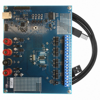
... IIN2+ IIN2- www.cirrus.com General Description The CDB5467U is an inexpensive tool designed to evaluate the functionality and performance of the CS5467 analog-to-dig- ital converter (ADC). The evaluation board includes an LT1019 voltage reference, a C8051F320 microcontroller with a USB in- terface, and firmware. The microcontroller controls the serial ...
Page 2
... Figure 18. Debug Panel ................................................................................................................ 27 Figure 19. Schematic - Analog Inputs ........................................................................................... 30 Figure 20. Schematic - CS5463 & Socket..................................................................................... 31 Figure 21. Schematic - Microcontroller & USB Interface............................................................... 32 Figure 22. Schematic - Power Supplies ........................................................................................ 33 Figure 23. Top Silkscreen ............................................................................................................. 34 Figure 24. Top Routing.................................................................................................................. 35 Figure 25. Bottom Routing ............................................................................................................ 36 Figure 26. Bottom Silkscreen ........................................................................................................ 37 2 CDB5467U TABLE OF CONTENTS LIST OF FIGURES DS714DB1 ...
Page 3
... Introduction The CDB5467U evaluation board provides a convenient means of evaluating the CS5467 power mea- surement IC. The CDB5467U evaluation board operates from a single +5V power supply. The evaluation board interfaces the CS5467 via a USB cable. To accomplish this, the board comes equipped with a C8051F320 microcontroller and a USB interface. Additionally, the CDB5467U GUI software pro- vides easy access to the internal registers of the CS5467 ...
Page 4
... Analog Section The CDB5467U evaluation board provides screw-type terminals (J21, J23, J27, & J28) to connect input signals to the voltage and current channels. The screw terminals are labels as VIN2-, VIN2+, VIN1-, VIN1+, IIN1+, IIN1-, and IIN2+, IIN2-. An R-C network at each channel input provides a simple anti-alias filter ...
Page 5
... The microcontroller interfaces the SPI of CS5467 with the USB connection to the PC, enabling the GUI software to access all the CS5467 registers and functions. Interface header, J40, is provided to allow the CDB5467U to be connected to an external energy registration device or an external microcontroller. To connect the CS5467 to an external microcontroller, R57, R58, R59, R60, R61, and R62 must be removed from the board ...
Page 6
... Jumper J9 allows the 8051_REGIN supply to be sourced from either the Vu+_EXT binding post (J6), +5V binding post (J3) or VD+_EXT binding post (J5). Power Supplies Analog (VA+) Digital (VD+) 8051 (Vu +3 Power Post Connections +5V GND VD+EXT VU+EXT +3.3 Table 4. Power Supply Connections CDB5467U VD+ 8051-REGIN VD+_EXT VD+ Vu+_EXT VD +3.3 VD+ VD+ (Default) (Default) O ...
Page 7
... Auto-boot Mode With a jumper connection on J18 (AUTO-BOOT ENABLE), the CS5467 operates in auto-boot mode and the CDB5467U board operates as a stand-alone system without attaching PC. When in auto- boot mode, a hardware reset (press on S1) will cause the CS5467 to boot up using the serial data from the serial EEPROM on the board (U10) ...
Page 8
... AN278. 2.2 Using the Software Before launching the software, check all jumper settings on the CDB5467U evaluation board as described in Section 1, and connect the board to an open USB port on the PC using the provided cable. Once the board is powered on, the software program can be launched. ...
Page 9
... See Figure 4. Check to verify that the USB cable is connected properly and the power supply is on and connected prop- erly to the CDB5467U. Reset the board (press the RESET button on the board) and try to setup the USB connection again. ...
Page 10
... Conversion Window, Pulse Rate Window, Data Collection Window, EEPROM Window, and Debug Win- dow. Each window provides a means to evaluate the different functions and performance of the CS5467. Each option has an associated function key (<F1>, <F2>, etc.). See Figure 6. 10 Figure 6. Menu Pull-down Options CDB5467U DS714DB1 ...
Page 11
... Quit Menu The Quit menu allows the user to exit the evaluation software. Upon selecting Quit, a message window appears and queries if exiting the evaluation software is desired. See Figure 7. DS714DB1 Figure 7. Quit Dialog CDB5467U 11 ...
Page 12
... Window pressing <F2> on the keyboard. In the Setup window, all of the CS5467's registers are displayed in hexadecimal notation and are decoded to provide easier readability. Refer to the CS5467 data sheet for information on register functionality and definitions. See Figure 8. 12 Figure 8. Setup Window CDB5467U DS714DB1 ...
Page 13
... HEX: field changing any of the values below the HEX: field to the desired set- tings. Although the CDB5467U software allows the user to modify any of the bits in the Config register, changing certain bits may cause the software and board to behave erratically. For the evaluation system to function properly, the IMODE, IINV field should be set to the default Active Low ...
Page 14
... The Refresh Screen button will update the contents of the screen by reading all the register values from the part good idea to press the Refresh Screen button when entering the Calibration window, or after modifying any registers to reflect the current status of the CS5467. 14 Figure 9. Calibration Window CDB5467U DS714DB1 ...
Page 15
... The gain register value(s) will automatically update when the calibration is completed. The Calibration window also contains the Power Offset Register1 / 2 display and adjustment. The user can read and write the values in the power offset registers (P1off / P2off). DS714DB1 CDB5467U 15 ...
Page 16
... The Mean and Standard Deviation columns will be updated every N cycles, where N is the number in the Samples to Average field. If the Samples to Average is set to a large number, it may take many collection cycles after pressing the Stop button before the data actually stops being collected. 16 Figure 10. Conversion Window CDB5467U DS714DB1 ...
Page 17
... In the CS5467, voltage 2 and temperature are multiplexed on one ADC channel. To initiate a temperature measurement, write 1 to the Tmeas register while in continuous conversion mode. When the Tmeas reg- ister returns to 0, the Temperature field should be updated with the data in the T (Temperature) register. DS714DB1 CDB5467U 17 ...
Page 18
... Start Button When the Start button is pressed, the CDB5467U will capture pulse rate data according to the values in the Integration Seconds and Periods to Average fields. After each integration period, the Pulse Count, Frequency, Average Freq., and Standard Deviation columns will be updated. The Average Frequency and Standard Deviation columns will only be updated after all the integrations have been collected ...
Page 19
... Refer to the Configuration Window section in this document for more information. 2.8.3 Collect Button This button will collect data from the part analyzed in the plot area. See the Collecting Data Sets section for more information. DS714DB1 Figure 12. Data Collection Window CDB5467U 19 ...
Page 20
... This field allows the user to select the number of samples to collect, between 16 and 32768. 2.8.7.2 Average When performing FFT analyses, this field determines the number of FFTs to average. FFTs will be col- lected and averaged when the Collect button is pressed. 20 Figure 13. Configuration Window CDB5467U DS714DB1 ...
Page 21
... Once the data has been collected, it can be analyzed, printed, or saved to disk. 2.8.9 Retrieving Saved Data From a File The CDB5467U software allows the user to save data to a file, and retrieve it later when needed. To load a previously saved file: 1. Pull down the Setup menu and select the Disk menu item. A file menu will appear. ...
Page 22
... The following is a description of the indicators associated with histogram analysis. Histograms can be plot- ted in the Data Collection Window by setting the analysis type pull-down menu to Histogram. 2.8.11.1 BIN Displays the x-axis value of the cursor on the histogram. 2.8.11.2 MAGNITUDE Displays the y-axis value of the cursor on the histogram. 22 Figure 14. Histogram Analysis CDB5467U DS714DB1 ...
Page 23
... Indicates for the variance of the current data set. The variance is calculated using the following formula: VARIANCE 2.8.11.6 MAXIMUM Indicates the maximum value of the collected data set. 2.8.11.7 MINIMUM Indicates the minimum value of the collected data set. DS714DB1 n 1 – ∑ Mean = --------------- - – 2 ∑ – Xi MEAN ----------------------------------------------- - – 2 ∑ – Xi MEAN ----------------------------------------------- - n CDB5467U 23 ...
Page 24
... Displays the y-axis value of the cursor on the FFT display. 2.8.12.3 S/PN Indicates the signal-to-peak noise ratio (decibels). 2.8.12.4 SINAD Indicates for the signal-plus-noise-plus-distortion to noise-plus-distortion ratio (decibels). 2.8.12.5 S/D Indicates for the signal-to-distortion ratio, 4 harmonics are used in the calculations (decibels). 24 Figure 15. FFT Analysis CDB5467U DS714DB1 ...
Page 25
... Data Collection Window by setting the analysis type selector to Time Domain (Figure 16). 2.8.12.9 COUNT Displays current x-position of the cursor on the time domain display. 2.8.12.10 MAGNITUDE Displays current y-position of the cursor on the time domain display. 2.8.12.11 MAXIMUM Indicates for the maximum value of the collected data set. DS714DB1 Figure 16. Time Domain Analysis CDB5467U 25 ...
Page 26
... Indicates for the minimum value of the collected data set. 2.9 EEPROM Window CDB5467U has an "Auto-Boot" demo feature that uses the on-board serial EEPROM, so that the CDB5467U can operate independently without being connected to a PC. CDB5467U GUI software also provides an EEPROM Window for reading & writing the serial EEPROM (Figure 17). ...
Page 27
... Debug Panel The Debug panel provides the user a way to access CS5467 registers and send commands to CS5467 directly (Figure 18). Refer to 5.15 in CS5467 data sheet for more details. DS714DB1 Figure 18. Debug Panel CDB5467U 27 ...
Page 28
... APPENDIX A. BILL OF MATERIALS 28 CDB5467U DS714DB1 ...
Page 29
... DS714DB1 CDB5467U 29 ...
Page 30
... APPENDIX B. SCHEMATICS 30 CDB5467U DS714DB1 ...
Page 31
... DS714DB1 CDB5467U 31 ...
Page 32
... CDB5467U DS714DB1 ...
Page 33
... DS714DB1 CDB5467U 33 ...
Page 34
... APPENDIX C. LAYER PLOTS 34 CDB5467U DS714DB1 ...
Page 35
... DS714DB1 CDB5467U 35 ...
Page 36
... CDB5467U DS714DB1 ...
Page 37
... DS714DB1 CDB5467U 37 ...
Page 38
... Cirrus Logic, Cirrus, and the Cirrus Logic logo designs are trademarks of Cirrus Logic, Inc. All other brand and product names in this document may be trademarks or service marks of their respective owners. LabWindows and CVI are registered trademarks of National Instruments, Inc. Windows, Windows 2000, and Windows XP are trademarks or registered trademarks of Microsoft Corporation. PADS and PowerLogic are trademarks of Mentor Graphics Corporation. 38 Changes Initial Release. CDB5467U DS714DB1 ...