STEVAL-ISA020V1 STMicroelectronics, STEVAL-ISA020V1 Datasheet - Page 10
STEVAL-ISA020V1
Manufacturer Part Number
STEVAL-ISA020V1
Description
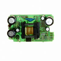
EVAL BOARD 3.5W BATTERY CHARGER
Manufacturer
STMicroelectronics
Type
Battery Managementr
Datasheets
1.VIPER12ADIP-E.pdf
(21 pages)
2.TSM101CDT.pdf
(13 pages)
3.STEVAL-ISA020V1.pdf
(6 pages)
Specifications of STEVAL-ISA020V1
Design Resources
STEVAL-ISA020V1 Gerber Files Battery Charger with TSM101 Bill of Material
Main Purpose
Power Management, Battery Charger
Embedded
No
Utilized Ic / Part
VIPer12AS, TSM101
Primary Attributes
3.5W, 0 ~ 7 V @ 500mA Out, Off-Line
Secondary Attributes
88 ~ 264 VAC
Input Voltage
88 V to 264 V
Output Voltage
0 V to 7 V
Product
Power Management Modules
Silicon Manufacturer
ST Micro
Silicon Core Number
VIPer12AS-E And TSM101
Kit Application Type
Power Management
Application Sub Type
SMPS
Kit Contents
Board
Rohs Compliant
No
Lead Free Status / RoHS Status
Lead free / RoHS Compliant
For Use With/related Products
VIPer12AS-E, TSM101
Other names
497-5519
Available stocks
Company
Part Number
Manufacturer
Quantity
Price
Company:

Part Number:
STEVAL-ISA020V1
Manufacturer:
STMicroelectronics
Quantity:
135


10/13
TSM101 integrates in the same 8 pin DIP or SO
package
outputs of the operationnal amplifiers
hibited thanks to an external pin.
An immediate way to take advantage of the high
integration and reliability of TSM101 is to use it as
a voltage and current controller on power supplies
secondary. The application note AN896 describes
precisely how to use TSM101 in an SMPS battery
charger.
The TSM101 Evaluation Board is adaptable to any
power supply or battery charger (SMPS or linear)
as a voltage and current controller with minimal
constraints from the user.
HOW TO USE THE TSM101 EVALUATION
BOARD ?
The generic Electrical Schematic is shown on fig-
ure 1. It represents an incomplete SMPS power
supply where the primary side is simplified.
Figure 1
one 1.24V precision voltage reference
two operationnal amplifiers
two diodes which impose a NOR function on the
one current source which can be activated/ in-
EVALUATION BOARD -TECHNICAL NOTE
The “IN+”and “IN-” power inputs of the evalua-
tion board should be connected directly to the
power lines of the power supply secondary.
The “Vcc” input of the evaluation board should
be connected to the auxiliary supply line.
In the case of an SMPS power supply, the “Reg”
output of the evaluation board should be connect-
ed to the Optocoupler input to regulate the PWM
block in the primary side. In the case of a linear
power supply, the “Reg” output should be con-
nected to the base of the darlington to regulate the
power output.
A diode might be needed on the output of the eval-
uation board in the case of a battery charger appli-
cation to avoid the discharge of the battery when
the charger is not connected.
COMPONENTS CALCULATIONS
The voltage control is given by the choice of the
resistor bridge R6/R7 (and the trimmer P1) due to
equation 1 :
where Vref = 1.24V
Vref = R6/(R6+R7)xVout
eq1
Related parts for STEVAL-ISA020V1
Image
Part Number
Description
Manufacturer
Datasheet
Request
R

Part Number:
Description:
BOARD RGB CTR ST7,STP08C596MTR
Manufacturer:
STMicroelectronics
Datasheet:

Part Number:
Description:
Power Management IC Development Tools Full Speed USB to RS232 Bridge Demo
Manufacturer:
STMicroelectronics
Datasheet:
Part Number:
Description:
Power Management IC Development Tools 2.5W solar eval BRD USB SPV1040 LD39050
Manufacturer:
STMicroelectronics
Datasheet:

Part Number:
Description:
BOARD EVAL FOR MEMS SENSORS
Manufacturer:
STMicroelectronics
Datasheet:

Part Number:
Description:
KIT DEV STARTER ST10F276Z5
Manufacturer:
STMicroelectronics
Datasheet:

Part Number:
Description:
BOARD EVAL HDMI $ VIDEO SWITCH
Manufacturer:
STMicroelectronics
Datasheet:

Part Number:
Description:
BOARD DEMO ACCELEROMETER DIL24
Manufacturer:
STMicroelectronics
Datasheet:

Part Number:
Description:
BOARD STLM75/STDS75/ST72F651
Manufacturer:
STMicroelectronics
Datasheet:

Part Number:
Description:
EVAL BOARD 3AXIS MEMS ACCELLRMTR
Manufacturer:
STMicroelectronics
Datasheet:

Part Number:
Description:
BOARD EVAL 8BIT MICRO + TDE1708
Manufacturer:
STMicroelectronics
Datasheet:
Part Number:
Description:
STMicroelectronics [RIPPLE-CARRY BINARY COUNTER/DIVIDERS]
Manufacturer:
STMicroelectronics
Datasheet:
Part Number:
Description:
STMicroelectronics [LIQUID-CRYSTAL DISPLAY DRIVERS]
Manufacturer:
STMicroelectronics
Datasheet:
Part Number:
Description:
BOARD EVAL FOR MEMS SENSORS
Manufacturer:
STMicroelectronics
Datasheet: