STEVAL-ISA020V1 STMicroelectronics, STEVAL-ISA020V1 Datasheet - Page 5
STEVAL-ISA020V1
Manufacturer Part Number
STEVAL-ISA020V1
Description
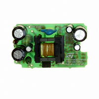
EVAL BOARD 3.5W BATTERY CHARGER
Manufacturer
STMicroelectronics
Type
Battery Managementr
Datasheets
1.VIPER12ADIP-E.pdf
(21 pages)
2.TSM101CDT.pdf
(13 pages)
3.STEVAL-ISA020V1.pdf
(6 pages)
Specifications of STEVAL-ISA020V1
Design Resources
STEVAL-ISA020V1 Gerber Files Battery Charger with TSM101 Bill of Material
Main Purpose
Power Management, Battery Charger
Embedded
No
Utilized Ic / Part
VIPer12AS, TSM101
Primary Attributes
3.5W, 0 ~ 7 V @ 500mA Out, Off-Line
Secondary Attributes
88 ~ 264 VAC
Input Voltage
88 V to 264 V
Output Voltage
0 V to 7 V
Product
Power Management Modules
Silicon Manufacturer
ST Micro
Silicon Core Number
VIPer12AS-E And TSM101
Kit Application Type
Power Management
Application Sub Type
SMPS
Kit Contents
Board
Rohs Compliant
No
Lead Free Status / RoHS Status
Lead free / RoHS Compliant
For Use With/related Products
VIPer12AS-E, TSM101
Other names
497-5519
Available stocks
Company
Part Number
Manufacturer
Quantity
Price
Company:

Part Number:
STEVAL-ISA020V1
Manufacturer:
STMicroelectronics
Quantity:
135


This technical note shows how to use the TSM101
integrated circuit with a switching mode power
supply (SMPS) to realize a battery charger.
An example of realization of a 12V Nickel-cadmi-
um battery charger is given.
1 - TSM101 PRESENTATION
The TSM101 integrated circuit incorporates a high
stability series band gap voltage reference, two
ORed operational amplifiers and a current source
(Figure 1)
Figure 1 : TSM101 Schematic Diagram
This IC compares the DC voltage and the current
level at the output of a switching power supply to
an internal reference.It provides a feedback
through an optocoupler to the PWM controller IC
in the primary side.
The controlled current generator can be used to
modify the level of current limitation by offsetting
the information coming from the current sensing
resistor.
A great majority of low or medium end power sup-
plies is voltage regulated by using shunt program-
mable voltage references like the TL431
(Figure 2).
A BATTERY CHARGER USING THE TSM101
The galvanic insulation of the control information
is done by using an opto-coupler in linear mode
with a variable photo current depending on the dif-
ference between the actual output voltage and the
desired one.
A current limitation is used to protect the power
supply against short circuits, but lacks precision.
This limitation is generally realized by sensing the
current of the power transistor, in the primary side
of the SMPS.
The role of the TSM101 is to make a fine regula-
tion of the output current of the SMPS and a pre-
cise voltage limitation.
The primary current limitation is conserved and
acts as a security for a fail-safe operation if a
short-circuit occurs at the output of the charger.
2 - PRINCIPLE OF OPERATION
The current regulation loop and the voltage limita-
tion loop use an internal 1.24V band-gap voltage
reference. This voltage reference has a good pre-
cision (better than 1.5%) and exhibits a very stable
temperature behavior.
The current limitation is performed by sensing the
voltage across the low ohmic value resistor R5
and comparing it to a fixed value set by the bridge
composed by R2 and R3 (Figure 3).
When the voltage on R5 is higher than the voltage
on R3 the output of the current loop operational
amplifier decreases. The optocoupler current in-
creases and tends to reduce the output voltage by
the way of the PWM controller.
The voltage regulation is done by comparing a
part of the output voltage (resistor bridge R6, R7
and P1) to the voltage reference (1.24V).
If this part is higher than 1.24V, the output of the
voltage loop operational amplifier decreases.
APPLICATION NOTE
5/13
Related parts for STEVAL-ISA020V1
Image
Part Number
Description
Manufacturer
Datasheet
Request
R

Part Number:
Description:
BOARD RGB CTR ST7,STP08C596MTR
Manufacturer:
STMicroelectronics
Datasheet:

Part Number:
Description:
Power Management IC Development Tools Full Speed USB to RS232 Bridge Demo
Manufacturer:
STMicroelectronics
Datasheet:
Part Number:
Description:
Power Management IC Development Tools 2.5W solar eval BRD USB SPV1040 LD39050
Manufacturer:
STMicroelectronics
Datasheet:

Part Number:
Description:
BOARD EVAL FOR MEMS SENSORS
Manufacturer:
STMicroelectronics
Datasheet:

Part Number:
Description:
KIT DEV STARTER ST10F276Z5
Manufacturer:
STMicroelectronics
Datasheet:

Part Number:
Description:
BOARD EVAL HDMI $ VIDEO SWITCH
Manufacturer:
STMicroelectronics
Datasheet:

Part Number:
Description:
BOARD DEMO ACCELEROMETER DIL24
Manufacturer:
STMicroelectronics
Datasheet:

Part Number:
Description:
BOARD STLM75/STDS75/ST72F651
Manufacturer:
STMicroelectronics
Datasheet:

Part Number:
Description:
EVAL BOARD 3AXIS MEMS ACCELLRMTR
Manufacturer:
STMicroelectronics
Datasheet:

Part Number:
Description:
BOARD EVAL 8BIT MICRO + TDE1708
Manufacturer:
STMicroelectronics
Datasheet:
Part Number:
Description:
STMicroelectronics [RIPPLE-CARRY BINARY COUNTER/DIVIDERS]
Manufacturer:
STMicroelectronics
Datasheet:
Part Number:
Description:
STMicroelectronics [LIQUID-CRYSTAL DISPLAY DRIVERS]
Manufacturer:
STMicroelectronics
Datasheet:
Part Number:
Description:
BOARD EVAL FOR MEMS SENSORS
Manufacturer:
STMicroelectronics
Datasheet: