STEVAL-ISA020V1 STMicroelectronics, STEVAL-ISA020V1 Datasheet - Page 9
STEVAL-ISA020V1
Manufacturer Part Number
STEVAL-ISA020V1
Description
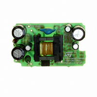
EVAL BOARD 3.5W BATTERY CHARGER
Manufacturer
STMicroelectronics
Type
Battery Managementr
Datasheets
1.VIPER12ADIP-E.pdf
(21 pages)
2.TSM101CDT.pdf
(13 pages)
3.STEVAL-ISA020V1.pdf
(6 pages)
Specifications of STEVAL-ISA020V1
Design Resources
STEVAL-ISA020V1 Gerber Files Battery Charger with TSM101 Bill of Material
Main Purpose
Power Management, Battery Charger
Embedded
No
Utilized Ic / Part
VIPer12AS, TSM101
Primary Attributes
3.5W, 0 ~ 7 V @ 500mA Out, Off-Line
Secondary Attributes
88 ~ 264 VAC
Input Voltage
88 V to 264 V
Output Voltage
0 V to 7 V
Product
Power Management Modules
Silicon Manufacturer
ST Micro
Silicon Core Number
VIPer12AS-E And TSM101
Kit Application Type
Power Management
Application Sub Type
SMPS
Kit Contents
Board
Rohs Compliant
No
Lead Free Status / RoHS Status
Lead free / RoHS Compliant
For Use With/related Products
VIPer12AS-E, TSM101
Other names
497-5519
Available stocks
Company
Part Number
Manufacturer
Quantity
Price
Company:

Part Number:
STEVAL-ISA020V1
Manufacturer:
STMicroelectronics
Quantity:
135


5.4. An example of application where the
charging current is different according to the
charging phase.
The following application includes a specific rec-
ommendation which requires that the charging
current should be fixed to Ich1 = 800mA in normal
charging conditions, and Ich2 = 200mA when the
cell voltage is below Vl=2.5V to optimize the cell
life-time.
Moreover, an Charging Status LED should be
switched off when the cell voltage is above
Vh=6.5V.
Figure 6 shows how this can easily be achieved
using an additional dual comparator (type LM393)
where the first operator (C1) is used to activate the
TSM101 internal current generator to offset the
current measurement thanks to R4, and the sec-
ond (C2) is used to switch the status LED off. On
figure 6, the status signal is determined by voltage
measurement, this could as well be achieved by
current measurement.
If V5 = 100mV is the maximum tolerable voltage
drop through the sense resistor R5 during normal
charging conditions, then the following calcula-
tions apply :
Figure 6 : Optimized Charging Conditions
Current Control :
R5 = V5 / Ich1 = 0.1 / 0.8 = 0.125
R5 = 125m
V5 = V
and V
R3 = 1k , R2 = 11.4k
V5 = R4 x Io + R5 x Ich2, therefore, R4 = (V5 - R5
x Ich2) / Io with Io = 1.4mA
R4 = 53.6
Vref = Vl x R15 / (R14 + R15) with Vl = 2.5V and
R14 + R15 ~ 20k
R15 = R14 = 10k
Voltage Control :
Vref = Vh x R6 / (R6 + R7) with Vh = 6.5V and
R6 + R7 ~ 12kW
R6 = 2.36kW, R7 = 10kW
Vref = Vh R17 / (R16 + R17)
R17 = 10kW, R16 = 42kW
Voltage Control :
Vref = Vh x R6 / (R6 + R7) with Vh = 6.5V and
R6 + R7 ~ 12kW
R6 = 2.36kW, R7 = 10kW
Vref = Vh R17 / (R16 + R17)
R17 = 10kW, R16 = 42kW
ref
ref
= 1.24V
x R3 / (R2 + R3) with R2 + R3 ~ 12k
TSM101/A
9/13
Related parts for STEVAL-ISA020V1
Image
Part Number
Description
Manufacturer
Datasheet
Request
R

Part Number:
Description:
BOARD RGB CTR ST7,STP08C596MTR
Manufacturer:
STMicroelectronics
Datasheet:

Part Number:
Description:
Power Management IC Development Tools Full Speed USB to RS232 Bridge Demo
Manufacturer:
STMicroelectronics
Datasheet:
Part Number:
Description:
Power Management IC Development Tools 2.5W solar eval BRD USB SPV1040 LD39050
Manufacturer:
STMicroelectronics
Datasheet:

Part Number:
Description:
BOARD EVAL FOR MEMS SENSORS
Manufacturer:
STMicroelectronics
Datasheet:

Part Number:
Description:
KIT DEV STARTER ST10F276Z5
Manufacturer:
STMicroelectronics
Datasheet:

Part Number:
Description:
BOARD EVAL HDMI $ VIDEO SWITCH
Manufacturer:
STMicroelectronics
Datasheet:

Part Number:
Description:
BOARD DEMO ACCELEROMETER DIL24
Manufacturer:
STMicroelectronics
Datasheet:

Part Number:
Description:
BOARD STLM75/STDS75/ST72F651
Manufacturer:
STMicroelectronics
Datasheet:

Part Number:
Description:
EVAL BOARD 3AXIS MEMS ACCELLRMTR
Manufacturer:
STMicroelectronics
Datasheet:

Part Number:
Description:
BOARD EVAL 8BIT MICRO + TDE1708
Manufacturer:
STMicroelectronics
Datasheet:
Part Number:
Description:
STMicroelectronics [RIPPLE-CARRY BINARY COUNTER/DIVIDERS]
Manufacturer:
STMicroelectronics
Datasheet:
Part Number:
Description:
STMicroelectronics [LIQUID-CRYSTAL DISPLAY DRIVERS]
Manufacturer:
STMicroelectronics
Datasheet:
Part Number:
Description:
BOARD EVAL FOR MEMS SENSORS
Manufacturer:
STMicroelectronics
Datasheet: